Download
1 / 15
150 likes | 151 Views
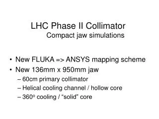
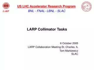
LARP Phase II Secondary Collimator RC-1. Collimator Development Status and Outlook Revised 03/16/09. Outline. Quick Review of SLAC Design Fabrication update Testing @ SLAC Proposed Testing @ CERN. Overview of SLAC Design. Jaw configuration

E N D
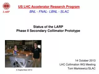
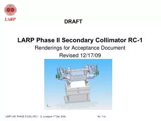
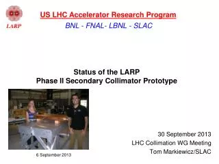
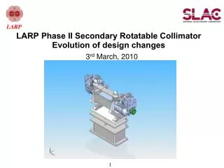
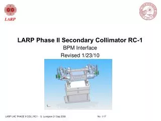
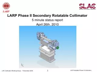
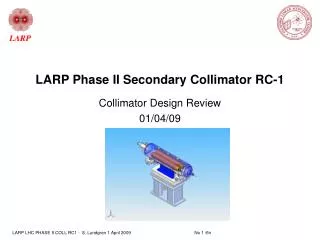
LARP Phase II Secondary Collimator RC-1 Collimator Development Status and Outlook Revised 03/16/09
Outline • Quick Review of SLAC Design • Fabrication update • Testing @ SLAC • Proposed Testing @ CERN
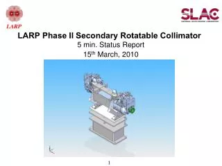
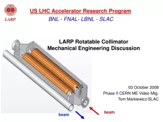
Overview of SLAC Design • Jaw configuration • Recapping: the 2mm annular gap between the Shaft and Jaw allows the Jaw ends to bend away from the beam centerline under beam heat load. • End Support System improvements • High strength stainless steel simplifies assembly and “beefs up” the support. • Rotation/Gear Drive Mechanism detail • Gear Drive now a separate piece. Permits simpler image current foil configuration. • Robustness Test cylindrical tank • Large diameter flanged ends allow access to moving parts.
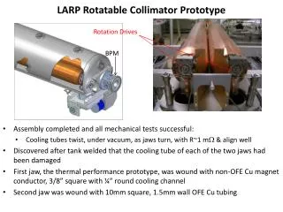
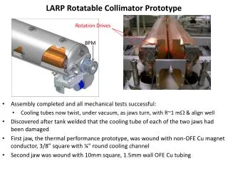
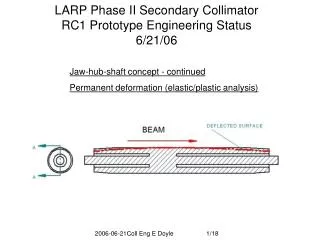
Jaw End Support System ~100 1mm dia. ball bearings in End adapter for rotation (Bellows removed to show support detail) Jaw Shaft End rests in slot of Support and is held by jam nuts on either side Flexible support is high strength stainless steel welded to bellows cuff during bellows fab Bellows mounting to Drive is unchanged from CERN design Cooling tube adapter is tig welded after Jaw is installed in Tank “Beefed-up” design still permits Jaw end-to-end offsets (3mm), Shaft thermal expansion and static sag. Deflection is improved for non-horizontal collimator positions.
Cutaway of Jam Nut and Support 100 1mm dia. Ball bearings roll in “V” groove Rotation Mechanism mounts to tab on bearing race Jam Nuts mate at beveled surfaces to strengthen tip of Support
Up Beam End with Image Current Foil Chain Tensioners used to clamp DN250 flanges to End Adapter Tank End Adapter (not shown) Beam centerline Ratchet actuator (not shown) mounts to tank floor Image Current Foil shadows gear drive mechanisms
Fabrication Update • 1st Glidcop Center Hub awaiting • copper plating and a final grooving • step prior to brazing to the Half Shafts. • Is in shop queue. • Final Moly Half Shaft promised ship date is • March 27th. • Glidcop Jaw material promised ship date also March 27th. • Mandrel fabrication is progressing well…. See next slide!
1st RC-1 Mandrel Prep for Grooving Rotation spreads lapidary wax Mandrel and Al strong-back set-up for waxing When wax cools parts bond together ensuring successful groove machining Heat parts again to separate. Strong-back was also heated and additional wax was added just prior to inserting into bore Link to complete set of photos: http://www-project.slac.stanford.edu/ilc/larp/rc/Photos
Grooving in work X,Y & Z axes 4th or “B” axis rotates
RC-1 and Robustness Test Drawing Status • Still a ways to go: • End Support and Bellows assembly fabrication • drawings in work now. • Robustness Test Tank Assembly fabrication • drawings planned for April and May.
RC-1 Near Term Plans • The 2 Mandrels needed for the LHC Test Assembly will • be released for quote after successful machining • on 1st Mandrel. • 1st Mandrel/Coil Assembly is planned for winding in April • Brazing in May • Facet machining in June
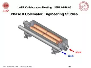
Drive Test Stand (CERN Drives) 1st RC-1 (when complete) RC-0 (Heater Test Jaw) Jaw and Support parts (plastic) are mocked up on the Drive Test Stand
Additional RF resistance tests Dummy Jaw End Assembly Tests to be performed with 1mm dia rhodium plated ball bearings (in actual configuration)will define the side load force needed for an acceptable resistance value. Perhaps the resultant force from the Image current foil/strap transverse displacement would be adequate.
Proposed TT60 Robustness Test Configuration • Preferred orientation is 0 degrees. • RC-0 & RC-1 Jaws are used. • Collimator mounts on CERN stand. • Cooling water quick connect? • Cables do not? • Laser micrometers mount here • for measuring possible permanent • distortion after beam strike • End ports are 1mm thick titanium. • Vacuum pump (if needed) mounts • to tee at down beam end. • Chain tensioners used on all flanges. Cameras mount here (both ends) for remote viewing surface damage to RC-1 Jaw after beam strike Beam DN250 flanges at ends permit access prior to test and after “cool-down period”
Proposed LHC Test comments • Planned orientation is 90 degree but could be adapted to that required by lattice position selected for our test. • Flanged ends are still planned for access to image current and moving parts prior to LHC Test and after “cool-down” period. • Cooling water and control cables mount with quick connects. • Square OFE copper is planned for cooling tube for LHC. • a braze tests is planned using round tubing in a round bottom groove to qualify the configuration. • we have been unable to locate a vendor willing to provide the • square i.d. square o.d. configuration in Cu-Ni necessary for flow rate spec. • Final determination of Tank shape will be made once RF modeling results are in.