Download
1 / 6
60 likes | 161 Views
LARP Phase II Secondary Rotatable Collimator. 5 min. Status Report 15 th March, 2010. CMM results: First Jaw (RC-0). Lots of data produced by CMM group. Summary: Looking at central 8 mm of each facet (all the beam will see) Worst facet flatness: 50.6 microns Average: 38.5 microns

E N D
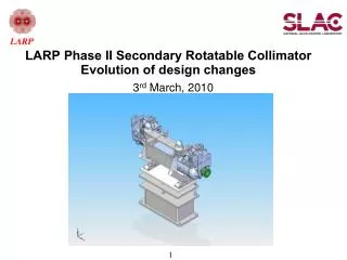
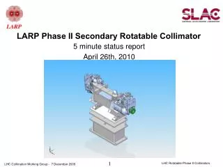
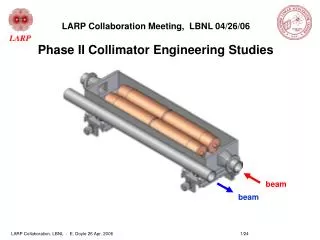
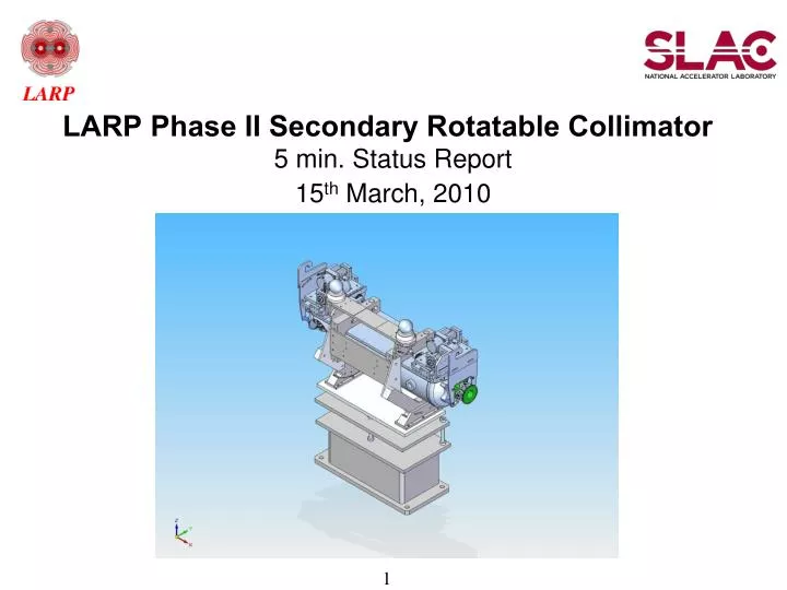
LARP Phase II Secondary Rotatable Collimator 5 min. Status Report 15th March, 2010
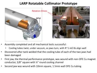
CMM results: First Jaw (RC-0) • Lots of data produced by CMM group. • Summary: • Looking at central 8 mm of each facet (all the beam will see) • Worst facet flatness: 50.6 microns • Average: 38.5 microns • Std dev: 10.3 microns • Generally exhibits a bowed shape where outer edges flair out
CMM results: Second Jaw (RC-1) • Second Jaw (RC-2) was machined to much greater precision • Summary: • Worst Facet: 10.8 microns! • Average: 8.25 • Std Dev: 1.45 • This is excellent!
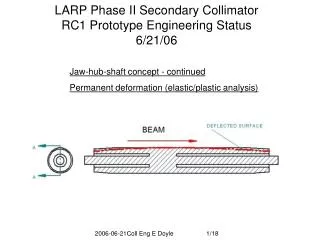
Facet offset and angles • Also measured width between each pair of facets and concentricity about rotation axis for RC-0 and RC-1. • This will give the new jaw edge with respect to beam axis after jaw rotation • Concentricity comparable to flatness values in previous slides • RC-1 much better than RC-0 • This says that there is little run-out and flatness dictates alignment of facets. • Angles of each facet also measured and within arcseconds of a perfect icosagon (20 sided polygon)
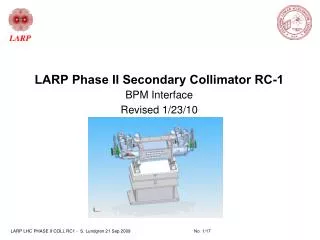
For BPM people:BPM Clearance for connectors Oliver requested we provide some figures showing the access space around the BPMs for connectors. Here are some pictures: