Download
1 / 34
340 likes | 348 Views
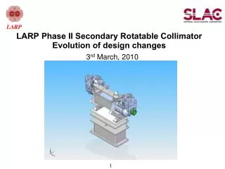
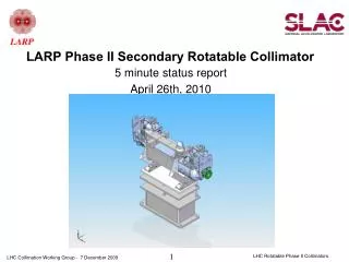
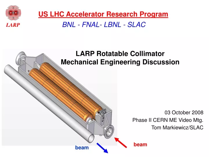
beam. beam. US LHC Accelerator Research Program. BNL - FNAL- LBNL - SLAC. LARP Rotatable Collimator Mechanical Engineering Discussion. 03 October 2008 Phase II CERN ME Video Mtg. Tom Markiewicz/SLAC. 2008-10-03 Discussion Questions.

E N D
beam beam US LHC Accelerator Research Program BNL - FNAL- LBNL - SLAC LARP Rotatable CollimatorMechanical Engineering Discussion 03 October 2008 Phase II CERN ME Video Mtg. Tom Markiewicz/SLAC
2008-10-03 Discussion Questions • Discuss your latest results of thermo-mechanical calculations for nominal working conditions (1h and 12 min. beam life time): • in which way is the "effective length" of the jaw under thermal load calculated ? • 2) Dimensioning of cooling pipes (material and size), water flow rate, water velocity (possible erosion/corrosion problems), temp increase of the water? • 3) Thermo-mechanical calculations for Asynchronous beam dump: • impact on TCP with shower on TCSM vs. direct impact on TCSM • have both cases been considered? • Discuss about method of calculation and results obtained. • Further analysis foreseen? • 4) Is any sensor foreseen to detect a beam impact on collimator jaws? • 5) Results of bake-out test? at which temperature was it performed? • 6) Use of any lubricant for moving parts under vacuum (bearings, Geneva mechanism...)? RC ME Questions - T. Markiewicz
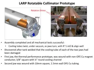
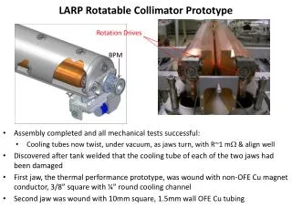
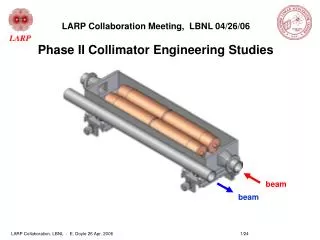
beam beam LHC Phase II Base Concept physical constraints current jaw design 20 facets • beam spacing: geometrical constraint • Length available 1.47 m flange - flange • Jaw translation mechanism and collimator support base: LHC Phase I • >10 kW per jaw Steady State heat dissipation (material dependent) Glidcop Cu Mo Cu coolant supply tubes twist to allow jaw rotation Helical cooling channels 25mm below surface Hub area Cantilever Mo shaft @ both ends RC ME Questions - T. Markiewicz
Results of Thermo-mechanical calculations for nominal working conditions • Large amount of data presented over 2004-2006 • Jaw Material selection: Copper • Continuous azimuthally wound cooling • Basic design “approved” by Assmann, Bertarelli et al summer 2005 • All calculations refer to the FIRST secondary downstream of primaries. Have discussed: • if copper RC placed here, increase aperture from 7 to 8 sigma • keeping only C-C Phase I secondary in this location • Design concept of “Jaw-Hub-Shaft” in 2006 improves performance under nominal 1hr and 12min beam lifetime conditions by x5 RC ME Questions - T. Markiewicz
June 2006Introduce newjaw-hub-shaftdesign whicheliminates central stop & flexible springs x5 improvement in thermal deformation 1260 um 236 um (60kW/jaw, t=12min) 426 um 84 um (12kW/jaw, t=60min) RC ME Questions - T. Markiewicz
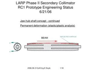
Comparison of Hollow Moly shaft to Solid Copper Shaft: Improved deflectionsbut necessitated Moly/Cu Brazing R&D Effective length defined by 100um sagitta RC ME Questions - T. Markiewicz
Dimensioning of cooling pipes (material and size), water flow rate, water velocity (possible erosion/corrosion problems), temp increase of the water? • Note location of most recent writeup: • http://www-project.slac.stanford.edu/ilc/larp/rc/FY07-Q2_RC_Design_Update.pdf • Tubing Variations Under Consideration • Copper Nickel tubing: need to test rigidity against winding on mandrel • Round tubing: 10mm OD, 8mm ID: • Note: In current square tubing design, wall is 1.5mm and top wall thinned by 0.25mm to 1.25mm total to prep surface for brazing to jaws RC ME Questions - T. Markiewicz
Jaw facets 2.5mm x 2.5mm elements Tmax = 57 e3 5mmmelt 3.3mm Shaft Shower max – extent of melted zone Cooling tubes Thermo-mechanical calculations for Asynchronous beam dumpPermanent deformation AND Molten copper Case: beam abort system fires asynchronously, 8 full intensity bunches into jaw Model: - increased resolution 3-D ANSYS & FLUKA models - Thermal heating/cooling analysis followed by quasi-static stress analysis - Jaw ends constrained in z during 200 ns, released for 60 sec cool-down - 0.27 MJ deposited in 200 ns - Molten material removed from model after 200 ns Result: - 57e3 peak temperature (ultra fine model) - 54 mm permanent deformation (concave) RC ME Questions - T. Markiewicz
Beam side 54 um In-plane permanent deflection Accident CasePermanent Jaw deflection, ux, after 60 sec cool-down Melted material removed After energy deposit (200ns – 60 sec), z-constraints released. Original analysis used this constraint at all times. • What happens to vaporized/melted • material? • - How to use deformed jaw? RC ME Questions - T. Markiewicz
Longitudinal Temperature Distribution of Collimator Hit with 9E11 7 Tev Protons Missteered beam (9E11 protons) 120 cm long copper secondary collimator jaw melting 25-30 cm Copper fractures @ ≈200 ˚C above Cu melting RC ME Questions - T. Markiewicz
Temperature Profiles of Hit & Adjacent Collimators Hit Collimator Adjacent Collimator Cross section at shower max. Copper Copper 2.5 cm 840 deg C Fracture temp. of copper is about 200 deg C RC ME Questions - T. Markiewicz
Another accident CaseBeam hits the horizontal primary collimator Copper 250 ˚C RC ME Questions - T. Markiewicz
Is any sensor foreseen to detect a beam impact on collimator jaws? • Not precluded • Would love to have a design contributed that we can incorporate • What are plans for this functionality in the CERN designs • What about “acoustic sensors”’ • Area of transition RF foil, which is stationary, is a possible location RC ME Questions - T. Markiewicz
Results of bake-out test? at which temperature was it performed? • Process: • “Standard” PEP-II Beamline bake-out sequence: • Vacuum vessel separately baked 200°C for several days • 3.7E-9 torr • Jaw H fired at 850°C before bake to accelerate bake-out process • Bake 200°C several days with 24 hour excursion to 300°C • paranoia • RGA Zero hydrocarbons • (mass >40) at 150 deg C • Final RGA & pressure on 6 Oct. RC ME Questions - T. Markiewicz
Vacuum Test Photos RC ME Questions - T. Markiewicz
Use of any lubricant for moving parts under vacuum (bearings, Geneva mechanism...)? • No lub on ceramic bearings • Moly disulfide on Geneva mechanism gears • Some parts of final Geneva will be ceramic RC ME Questions - T. Markiewicz
NLC Consumable Collimatorrotatable jaws – 500 to 1000 hits Note short high-Z material. < 10 W per jaw =>radiative cooling! 6.0 Aperture control mechanism – 5mm accuracy & stability Movers align chamber to beam based on BPMs Alignment BPMs upbeam & down RC ME Questions - T. Markiewicz
SLAC Timeline for RC=Rotatable Collimator PrototypeGene Anzalone, Yunhai Cai, Eric Doyle, Lew Keller, Steve Lundgren, Tom Markiewicz, Jeff Smith • 2004: Introduction to project • 2005: Conceptual Design Phase II RC using FLUKA, Sixtrack and ANSYS, External Design Review, collimator test lab set up • 2006 Improved Conceptual Design, hire full time ME and designer, fabricate tooling, 2D/3D drawings of test and final parts, braze two short test pieces • 2007: Examine test brazes, braze and examine 3rd short test piece, develop and build rotation mechanism, design RF shield, fab 1st full length jaw; hire first postdoc • 2008 Thermal tests of single jaw, fabricate two more jaws and assemble into a vacuum tank compatible with Phase I adjustment mechanism = RC • 2009: Mechanically test RC, ship and install in SPS/LHC • 2010: Collimator tests at LHC & Final drawing package for CERN • 2011: Await production & installation of chosen design(s) by CERN • 2012: Commissioning support • Main Deliverables • Thermal tests of single collimator jaw • Construct and mechanically test full RC prototype to be sent to CERN RC ME Questions - T. Markiewicz
FLUKA Results - Power Deposited vs. Length • Ist secondary collimator • Various materials 4 x 10¹¹ p/s lost RC ME Questions - T. Markiewicz
Cooling Beam heating This side expands due to heating Expansion of jaw’s beam side causes bending toward beam DT Dominant collimator specifications • 25mm maximum deformation toward beam • 7 s nominal aperture • The first long secondary collimator may be set at 8s to ensure 25 mm intrusion with respect to 7 s • 45 mm minimum aperture jaws fully retracted • Beam spacing limits transverse dimensions • Maximum length predetermined: 1.48 m flange-flange • No water-vacuum joints Thermal expansion is the problem This effect is a function of material, jaw OD & ID, length, and cooling arrangement RC ME Questions - T. Markiewicz
FLUKA ANSYS 25mm 80mm Basis for Design ChoicesANSYS Thermal/Mechanical simulations using FLUKA energy deposit • 10x10x24 FLUKA bins mapped to ANSYS elements, one for one • Energy density of FLUKA bin applied to ANSYS element X RC ME Questions - T. Markiewicz
Material thermal performance- Hollow Cylinder Model- O.D = 150 mm, I.D. = 100 mm, L = 1.2 m- NLC-type edge supports- aperture 10s * * Promising but no practical implementation Cu chosen – balance of efficiency, deflection and manufacturability RC ME Questions - T. Markiewicz
Justification of Cu Choice Cu chosen as best balance between collimation efficiency, thermal distortion & manufacturablity RC ME Questions - T. Markiewicz
Specification Changes Relative to April 2006 Design RC ME Questions - T. Markiewicz
IR-7 Beam 2 Beam 1 dipoles First group of secondary collimators Primary collimators 40 m RC ME Questions - T. Markiewicz
Heat deposited in major components (W/m^3) in 1 hr beam lifetime operation RC ME Questions - T. Markiewicz
Major jaw dimensions and calculated cooling performance RC ME Questions - T. Markiewicz
Vacuum Bake of 1st 200mm Test PieceResults: 4/1/07~3x over LHC Spec • 1st Jaw Braze Test Assembly has been vacuum baked at 300 degrees C for 32 hours. • LHC Requirement = 1E-7 Pa = 7.5E-10 Torr • Baseline pressure of Vacuum Test Chamber: • 4.3E-7 Pa (3.2E-9 Torr) • Pressure w/ 200mm Jaw Assy. in Test Chamber: 4.9E-7 Pa (3.7E-9 Torr) • Presumed pressure of 200mm lg. Jaw Assy.: 6.0E-8 Pa (4.5E-10 Torr) • Note: above readings were from gauges in the foreline, closer to the pump than to the Test Chamber. Pressures at the part could be higher. • Outcome: • SLAC vacuum group has suggested longitudinal grooves be incorporated into the inner length of jaws; incorporated into next prototype RC ME Questions - T. Markiewicz
Braze Test #3: 8 ¼-round jaws to mandrel/coil 19 June 2007: After 1st Jaw BrazePrepped for 2nd Braze to fillup jaw-jaw joints 14 June 2007: Jaw Fit Up RC ME Questions - T. Markiewicz
Braze Test #3: Vacuum tests: No improvement • 3rd Jaw Braze Test Assembly has been vacuum baked at 300 degrees C for 32 hours. Results in slightly lower pressure. • Inclusion of longitudinal groovesin the inner length of jaws for better outgasing • Test Chamber setup similar to previous test. Under Investigation... RC ME Questions - T. Markiewicz
Exact Nature & Extent of Damaged Region Thin Cu sample in FFTB electron beam at SLACHole = Beam Size 2000um 500 kW 20 GeV e- beam hitting a 30cm Cu block a few mm from edge for 1.3 sec (0.65 MJ) FNAL Collimator with .5 MJ RC ME Questions - T. Markiewicz
Cross Section at Shower Maximum Showing CopperMelting and Possible Fracture Regions in a Mis-steering Accident 3D ANSYS model, E. Doyle Copper Jaw Fracture zone, radius = 7 mm 2.5 cm Melting zone (grey), radius = 3.3 mm RC ME Questions - T. Markiewicz
Cross Section at Shower Maximum Showing CopperBoiling in a Mis-steering Accident 3D ANSYS model, E. Doyle Copper Jaw 2.5 cm Boiling zone (grey), radius = 2.2 mm RC ME Questions - T. Markiewicz