Download
1 / 20
200 likes | 319 Views
TEST MODULE WG Cradles for CLIC module supporting system. 04-07-11. SUMMARY Introduction : different types of cradles Requirements Boostec cradles Epucret cradles Conclusion: next steps concerning cradles. Introduction: girders and MB quad support.

E N D
TEST MODULE WGCradles for CLIC module supporting system H. MAINAUD DURAND, N. CHRITIN 04-07-11
SUMMARY • Introduction: different types of cradles • Requirements • Boostec cradles • Epucret cradles • Conclusion: next steps concerning cradles
Introduction: girders and MB quad support • Several components will be pre-aligned on supports: • Along the MB: Along the DB: • RF structures on girders PETS + DB quad on girders • MB quad on interface plate DB and MB girders will be interlinked with their extremities, based on so-called cradle. This allows a movement in the transverse girder interlink plane within 3 degrees of freedom (“articulation point between girders”). (Longitudinal direction adjusted thanks to a mechanical guiding). MB quad is mounted on an interface plate, allowing an adjustment along 5 degrees of freedom (longitudinal position will be positioned manually).
Introduction: test module and cradles M Epucret S M Boostec S M Boostec S M Epucret S M S/M ? M S M C M S M C M M Master side Installed Ordered S Slave side To be designed 4
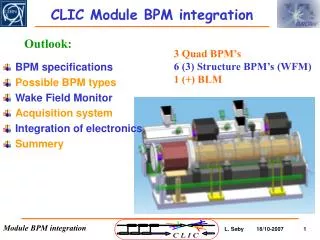
Introduction: terminology Girder Ves Targets for fiducialisation Cradle Linear actuators Sensors Longitudinal adjustment Mechanical pre-alignment 5
Requirements : main data • Adjacent girders will be interlinked with their extremities (so called cradle), allowing a movement in the transverse girder interlink plane within 3 degrees of freedom (X, Y, roll) • Colinearity of mean axis of Ves on two adjacent girders: 5 um, along X and Y axes in the transverse girder interlink plane 6
Requirements : main data • Longitudinal positioning of +/- 0.3 mm will have no impact on the articulation point • Each extremity of a girder equipped with a cradle • On each cradle: several interfaces, positioned within 0.1 mm, and measured within 5 μm w.r.t mean axis of Ves. • Once one girder is installed, the second shall be installed from the top, with no interferences with supports and stretched wires already in place • Area protected : stretched wires • Interchangeability between cradles. 7
Requirements : interfaces With sensors: • Each cradle hosts the following sensors: • 1 cWPS, screwed on a 3 balls interface • 1 oWPS, screwed on a 3 balls interface • 1 inclinometer, screwed on a 3 balls interface • 1 temperature probe, inserted in a hole with a diameter of 4.1 mm • Cradles must be rigid and stable in time, with no difference in their shape when equipped or not with sensors (deformations < 2 μm) • Slave and Master cradles equipped for test module. Once everything is validated, only master cradles will be equipped. 8
Requirements : interfaces With girders: Reference surfaces for Boostec: one side / one below Reference surfaces for Epucret: one above / one side Boostec Epucret 9
Requirements : interfaces With actuators: Each cradle supported by 2 vertical linear actuators, already ordered, and on radial linear actuator. Range of each linear actuator: +/- 3 mm, resolution < 1 μm With mechanical pre-alignment: Manual adjustment in longitudinal: +/- 0.4 mm, resolution 10 μm With articulation point: • Constraints and external forces applied: • Vacuum • Waveguides 10
Boostec cradles Design of the articulation point 11
Boostec cradles Design of the Boostec cradle: 12
CONCLUSION • First cradles installed are being tested in 169. Results are promising. Tests under progress • Qualification of concept of articulation point (Micro-contrôle versus Boostec/CERN: • Metrological evaluation • Behavior of the articulation point w.r.t micrometric displacements, w.r.t larger displacements (+/- 1 mm) • Impact at beam level • Impact of displacements on adjacent articulation points • Validation of algorithm of repositioning • Implementation of active pre-alignment 15
CONCLUSION • Rigidity and stressmeasurements on 3 pieces foreseen this summer, to validate the theoretical study • Epucret cradles received (under CMM measurements), other mechanical parts (mechanical pre-alignment, articulation points) ordered last week, to be delivered end of July 2011. • Technical note will be ready end of July. 16
For a force applied of 10 N (micrometric screw) at the level of the hole (blue area), we have a displacement of 7.5 mm. At the output, we have a displacement of 0.3 mm.
Elongation of 0.053 mm under a load of 400 kg Constraints in “ailettes” under load, with a displacement of 2 mm
Pivot under load and inclined (one vertical actuator at 3 mm, the other one at – 3 mm)