Download
1 / 28
290 likes | 440 Views
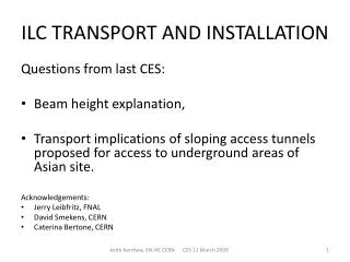
CLIC MODULE TRANSPORT AND INSTALLATION. Keith Kershaw CES, 8 October 2008. AIMS. REVIEW REQUIREMENTS AND PROPOSE CONCEPTUAL SOLUTION FOR LOWERING AND UNDERGROUND TRANSPORT / INSTALLATION OF CLIC MODULES. THIS CONCEPTUAL DESIGN WILL BE AN INPUT INTO THE TUNNEL INTEGRATION STUDIES. APPROACH .

E N D
CLIC MODULE TRANSPORT AND INSTALLATION Keith Kershaw CES, 8 October 2008
AIMS • REVIEW REQUIREMENTS AND PROPOSE CONCEPTUAL SOLUTION FOR LOWERING AND UNDERGROUND TRANSPORT / INSTALLATION OF CLIC MODULES. • THIS CONCEPTUAL DESIGN WILL BE AN INPUT INTO THE TUNNEL INTEGRATION STUDIES
APPROACH NEED TO CONSIDER : • TRANSPORT ALONG TUNNEL • TRANSFER AND INSTALLATION ON SUPPORTS • LOWERING FROM SURFACE AND ENTRY INTO TUNNEL • 20,000 MODULES SO NEED TO BE FAST. • ALLOW INDIVIDUAL MODULE EXCHANGE Previous presentations reviewed transport and installation solutions used elsewhere
Transport questions + answers MODULE CONDITIONING FOR TRANSPORT • What is the unit of transport? -one module –see later slides • Dimensions in transport configuration - see later slide • Weights in transport configurations-1500kg • Potential lifting points (e.g. for transfer) –consider lifting points above module – allow space for spreader beam • Potential support points – support under girders during transport TRANSFER TRAJECTORY RESTRICTIONS • What supports etc will already be installed on the floor? – see later slides • How much clearance space between adjacent modules during transfer/installation- 30mm allowed for interconnections – space available during installation to be defined POSSIBLE SIMULTANEOUS TRANSPORT/INSTALLATION OF SEVERAL INTERCONNECTED MODULES • What are the possibilities/implications if several modules are interconnected on the surface and transported/ installed at same time? –support and survey concepts based on module installation one at a time VIBRATIONS • Is it reasonable at this stage to assume that the levels of precaution taken for cryodipole tunnel transport will be sufficient? - 1g used as basis (i.e. normal handling techniques) note: need to avoid overloading supports during installation.
Transport envelope in cyan – 1125 x 1150 x 2100 Lifting points according to the worst case, i.e. on top of the transport envelope. Intergirder support acceptable assumption for the moment. R. Nousiainen 04092008
Assembly, Transport and Installation Continuation of the meeting held on 28th of August 2008 K. Kershaw, H. Mainaud Durand, R. Nousiainen, G. Riddone, T. Touze (R. Nousiainen slides)
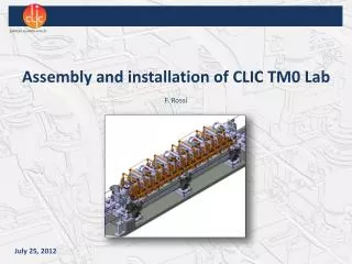
Step 1 • Assembly at surface • Use the same configuration • as in the tunnel • - MB-DB interconnections installed • - Fiducialisation done
Step 2 Add installation and transportation supports
Step 3 Move module to a transportation support
Step 4 Tunnel before module installation - Prepare propagation network reference and pre-align supports
Step 5 Module at the installation point. - Use temporary supports for installation.
Step 5b Module at the installation point. - Use temporary supports for installation.
Step 6 Module installation trajectory 500
Step 7 Installed module with temporary supports
Step 7b Installed module - Temporary supports removed
CLIC 3-D Studies for module Transport and Installation INSTALLATION MODULES Keith Kershaw / John Osborne / A.Kosmicki 2008 Sept. 25th
RIGHT VIEW TYPICAL CROSS SECTION CLIC TUNNEL
Vehicle conceptual design • Floor – running vehicles with on-board (un)loading cranes. • Transport several modules at a time • Avoid requirement for reserved space below beams / girders • Modular: vehicle base with separate operator cabins and interchangeable lifting equipment modules • Monorail for power (+ buffer batteries) • 1200 wide x 2270 high x 12m long (+ 2.5m for cabs) • Allows reservation of space in tunnel for transport and transfer of modules (however module beam offset issues may change transfer height)
Main beam Drive beam 2 CV pipes 250mm Turnaround loop Monorail 3 cable trays 520mm 2 CV pipes 600mm Safe passage Transport train Drive beam Main beam RIGHT VIEW TYPICAL CROSS SECTION CLIC TUNNEL
Main beam Drive beam 2 CV pipes 250mm Turnaround loop Monorail 3 cable trays 520mm 2 CV pipes 600mm Safe passage Transport train Drive beam Main beam RIGHT VIEW TYPICAL CROSS SECTION CLIC TUNNEL
Main beam Drive beam 2 CV pipes 250mm Turnaround loop Monorail 3 cable trays 520mm 2 CV pipes 600mm Safe passage Transport train Drive beam Main beam RIGHT VIEW TYPICAL CROSS SECTION CLIC TUNNEL
Main beam Drive beam 2 CV pipes 250mm Turnaround loop Monorail 3 cable trays 520mm 2 CV pipes 600mm Safe passage Transport train Drive beam Main beam RIGHT VIEW TYPICAL CROSS SECTION CLIC TUNNEL
Lowering of modules etc • Use lifts for fast lowering of modules • Method of fast loading of modules onto vehicles • Space to allow loaded vehicles to queue before driving along tunnel (-e.g. grouped passage through interconnection work sites) • Space for maintenance /repair • Passing places to allow sorting of vehicles/modules
Jonction chamber with shielding Shaft Loading area Maintenance area 10t Crane Services area 3D models are based on Civil Engineering drawings prepared in 2007
Logistics – indicative figures • 20,549 modules to install (assume supports already in place) • Access shafts 5km apart • Consider 1 vehicle with 4 modules • Driving speed 4km/h • Consider mid-sector (2.5km driving each way ) • Ignore loading time (queuing) • Driving time = 2 x 2.5/4 =1.25hrs • Unloading / installation time = say ½ hr x4 = 2hrs • 1 shift → 8 modules with one vehicle • 20549 modules in 2 years (single shift, weekdays) → ~41/day → need min 6 operational vehicles for modules
Next steps • Agree concept as basis for further work –feedback from other groups • Continuous review and refinement as more details of modules and supports and other items and services become available • Consider transport and installation of: • Overhead magnets • Turnarounds • Beam dumps • Services