Download
1 / 16
160 likes | 234 Views
CLIC Module Instrumentation. Beam position monitors Baseline solutions Status Next phase of R&D Beam loss monitors Baseline solutions Next phase of R&D Module acquisition system Status Next phase of R&D Status and outlook. Beam Position Monitors - Baseline.

E N D
CLIC Module Instrumentation • Beam position monitors • Baseline solutions • Status • Next phase of R&D • Beam loss monitors • Baseline solutions • Next phase of R&D • Module acquisition system • Status • Next phase of R&D • Status and outlook CLIC Module Working Group
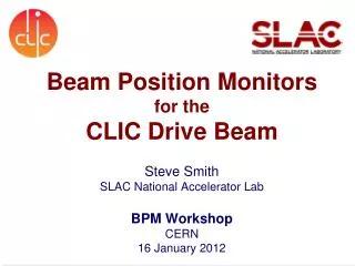
Beam Position Monitors - Baseline High accuracy (5um) resolution (50nm) BPM in Main Linac and BDS Very high numbers of BPMs for the DB decelerator, together with high accuracy CLIC Module Working Group
Beam Position Monitors - Baseline CLIC Module Working Group
Main Beam Cavity BPM, Baseline Dipole-mode “BPM” resonator& waveguide With fiducial Monopole-mode “REF” resonator • WG-loaded, low-Q X-Band design (Fermilab-CERN-RHUL) • Qℓ ≈ 260, resonator material: 304 stainless steel • CTF prototype includes a monopole mode reference cavity (same frequency) • ~50 nsec time resolution, <50 nm spatial resolution • Calibration ports can be used for signal redundancy if required CLIC Module Working Group
Status on CLIC Cavity BPM • Two existing designs for CLIC and CTF3 (change in resonant frequency) • Prototype for CTF3 (15GHz) under fabrication : Metrology done (out of tolerance). Need to find other manufacturer (RIAL) • Lab tests end 2011, followed by brazing and more tests…modifications…new prototypeTest foreseen end 2012 on Califes Beam line. • Fabrication of Mock-ups for Lab modules (T1, T4) will be launched mid 2012. • Integration into module done. • CLIC cavity BPMs would have to be adapted to the change in beam pipe diameter in the BDS Dipole cavity From Rogelio CLIC Module Working Group
Drive Beam Decelerator BPM, Baseline • Striplines BPM for the CLIC decelerator • High current 100A – high bunch frequency 12GHz • In the vicinity of an RF strucutreproducing 100MW @12GHz • Temporal resolution of 10ns • 2 micron resolution over an aperture of 23mm (accurate calibration) • Transverse mode damped by SiC absorber Diameter: 23 mm, Striplinelength: 25 mm Impedance: 50 Ohm By Steve Smith Simulations of transverse wakes CLIC Module Working Group
Status On Drive Beam BPM • Mock-ups manufactured for the two T0 lab-modules. For Lab. T1, T4, four BPS manufactured by IFIC are at CERN. • Prototype for lab tests being manufactured. • Lab tests end 2011, …modifications?…new proto type?. • Test foreseen end 2012 on TBL. • Integration into module done. Mock-up BPS CLIC Module Working Group
Plans CLIC BPM during the PPP • Drive Beam BPM – design Collaboration with • Prototype(s) to be tested on the Test Beam Line at CTF3, and compared with inductive BPMs. • Test of module acquisition system with BPMs developed by LAPP. • Look for industrialization and cost optimization • Follow evaluate alternative designs like coaxial BPM designed by Igor. • Main Beam cavity BPM – design Collaboration with & • Simulation of wakefieldand interference due to the presence of high field in the accelerating structure. Choke mode BPM • Demonstrate high resolution and high bandwidth • Prototype under-construction: Cavity BPM and its read-out electronic • Test at CTF3 in CLIC module in Two-beam Test stand • Demonstration of high spatial resolution @CTF3 and ATF2 • Evaluate the performance of the BPM during the temperature changes occurring the main tunnel during the operation of the CLIC (~20degrees) CLIC Module Working Group
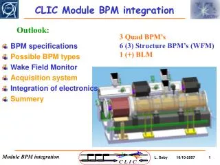
Beam Loss Monitors : Baseline • Two beam modules: 1 Ionisation chamber per Quadrupole • 41484 Quadrupoles in DB • 4020 Quadrupoles in MB CLIC Module Working Group
Beam Loss Monitors : PPP • Beam losses simulations using Monte-carlo code (FLUKA) • Establish limit for damage in rest of accelerator complex • - Destructive losses on the Drive Beam or the Main beam when 1% (1.5 1012 part.) or 0.03% (3.5 1010 part.) of a single bunch train hits a single aperture restriction. • Development the detection system • Difficulty to identify the source of the loss in the CLIC modules (Drive beam or Main beam) • DB • Look for cheaper detector than Ionization chambers using Cerenkov fibers Drive Beam losses Main Beam losses MB Low energy By, S.Mallows CLIC Module Working Group
Plans for BLM Studies during the PPP • Study the loss pattern in the CLIC module and define the best detection system (FLUKA) • Design an test a system capable of identifying losses from Main and Drive beams • Study and develop the Beam loss monitoring system for Damping ring By E.B.Holzer, J.van Hoorne, S.Mallows CLIC Module Working Group
General specifications of a local acquisition system • Since 2008 we work on the CLIC module acquisition in • collaboration with CERN (Lars Soby). • → about 200 signals to be acquired every 2m for the • 7 sub-systems. • Most versatile solution: industrial crate with • 1 service board: autonomous 12VDC power supplies performed from 230VAC line, network access and distribution on back-plane. • Several standard instrumentation boards: simple architecture based on FPGA and mezzanines: different mezzanines developed for the different subsystems with a standard interface (FPGA high speed connectors). By S. Vilalte CLIC Module Working Group
Possible global architecture NETWORK Device 1 Device n PCIe 1 PCIe 2 PCIe n Possible timings Surface GBT links Tunnel Crate 1 Crate 2 Crate 3 Crate 4 Crate n 230VAC line By S. Vilalte CLIC Module Working Group
Mezzanine developments Mezzanine Mother board • Results: • ADC: SNR=72dB, SINAD=71,2 so 11,5 enob @100Msps. • Amplifier OK. • HSMC connector OK. • Jitter cleaning and channels synchronization OK. By S. Vilalte CLIC Module Working Group
Surface data recovering-PCIe • Results: • All links tested up to 8,5Gbps. • ADC synchronization tested with success. • Works well currently with USB, PCIe IP to be implemented (end 2011). Should be ready for beam tests end 2012 By S. Vilalte CLIC Module Working Group
Status and outlook Mock-ups for lab test modules ready for the DB, but not for MB on T1 and T4. Proto types of both DB and MB BPMs ordered, and electrical tests in laboratory for both BPMs by end of 2011. BPM development is ongoing in collaboration with Fermilab, RHUL (MB BPM) and IFIC (DB BPM) No BPMs ordered for CLEX modules, but believe should be OK for end 2012. BLM development has really started and is evolving fast. Development of module acquisition system well advance and should be ready for beam tests end 2012, but still no space foreseen in CLIC tunnel!! CLIC Module Working Group