Download
1 / 31
570 likes | 1.63k Views
Summary of Bump Bonding Techniques for Pixel Systems. M. Lozano, E. Cabruja, A. Collado. Centro Nacional de Microelectrónica Barcelona (Spain). INDEX. Pixel systems Summary of bump bonding techniques Technology comparison and forecasts Testing issues Thermal issues Conclusions.

E N D
Summary of Bump Bonding Techniques for Pixel Systems M. Lozano, E. Cabruja, A. Collado Centro Nacional de Microelectrónica Barcelona (Spain)
INDEX • Pixel systems • Summary of bump bonding techniques • Technology comparison and forecasts • Testing issues • Thermal issues • Conclusions
Pixels systems • Pixel detector chip • Two dimensional diode array • Material: Si, diamond, SiC, GaAs, CdTe, CdZnT • Electronics chip • Built on a separate substrate • Provides: Amplification, data storage, data compression, communication • Pixel detector bonded to electronics
Pixel systems • Small pixel size (50 -250 µm) • High number of pixels (100 - 10 000) • Very low leakage current • Low cross talk between pixels • Unaffordable with conventional bonding technologies • Ideally suited for bump bonding flip chip technology • Not commercially available (yet) Many difficulties to be solved
Process steps: Direct bonding Rerouting Detector and/or amplifier chips Under Bump Metallisation (UBM) Bumping On detector or on amplifier chip, depending on the application Flip chip Reflow, anneal o adhesive bonding Underfilling Bump bonding flip chip technology
Rerouting Adapt pad distribution between detector and electronics chips Material: Al Up to 4 layers High reliability (99.8%) Increase cost Best to adjust pixel and amplifier size to avoid it Dielectric choice Inorganic Deposited SiO2, Si3N4 Spin-on glass (SOG) Organic: Polyimide Photosensitive polyimide Reduce complexity and cost. Another choice for the detector: no passivation Rerouting
Aluminum not suitable for direct bump bonding Al2O3 passivation layer Au-Al intermetallics Process steps (mod. 1) Sputter etching metal layers Normal photolithography Metal etching Process steps (mod. 2) Spin on 5 µm photoresist Sputter etching metal layers Lift off Metal layers : 1st: Diffusion barrier and adherence 2nd: Soldering 3rd: Passivation for 2nd layer Examples: Ti/Ni/Au Ti/Au/Cu/Au Under Bump Metallisation (UBM)
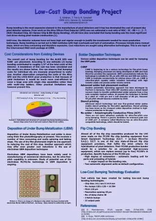
Bumping technologies • Evaporation through mask • Evaporation with thick photoresist • Screen printing • Stud bumping (SBB) • Electroplating • Electroless plating • Conductive Polymer Bumps
Evaporation through mask (C4) • Process steps • Mask alignment • Sequential evaporation of • Thin UBM layer: Cr/Cr-Cu/Cu/Au • Ball: Pb/Sn • Reflow into spheres • Characteristics • Proprietary of IBM • Need for a metallic mask • Pitch 200 µm • Bump height 100 - 125 µm • Expensive
Process steps Spin on thick photoresist (30 - 60 µm) Sequential evaporation of Thin UBM layer: Cr/Cr-Cu/Cu/Au Ball: Pb/Sn Lift off photoresist Reflow into spheres Characteristics Variation of previous method Higher pitch Evaporation with thick photoresist
Screen printing • Process steps • Stencil alignment • Solder paste deposition with a squeegee • Reflow into spheres • Characteristics • Minimum pitch: 200 µm • Stencil printing thickness: 100 - 50 µm Same bump height • Solder pastes: • Sn/Pb, Sn/Pb/Ag, Sn/Ag, Sn/Sb • Pb free pastes: In, Pd, Sn/Ag/Cu • Most widespread • Very high yield
Process steps Sequential creation of a ball with a ball bonder and ball bond Overall planarisation of bumps Optional reflow into spheres Charactersitics Ball material: Au (Pb free) Min. ball size: 45 µm (3 wire ) Min. pitch: 70 µm No need for UBM in substrate Usable in single chips No self alignment Cheap, but low throughput Stud Bump Bonding Solder Ball Bumping SBB Stud bumping (SBB)
Electroplating bump bonding • Process steps • Ni/Au sputtering over the whole wafer • Photolithography to delimit bump areas (thick photoresist) • Electrolytic deposition: • Cu layer • Pb/Sn bumps • Photoresist elimination • Etch wafer metalisation • Reflow into spheres
Characteristics Other bump materials: Au Au/Sn The plating process can induce wafer stress Equipment compatible with other microelectronic technologies Minimum pitch 40 µm Bump height 30 - 75 µm Difficulties: Bump height highly dependent in current density Variations in current density across the wafer gives non uniformity in bump height Difficult in using thick photoresists Deposit Align Exposure Electroplating bump bonding
Process steps Pad conditioning Zinkation Bump electroless deposition Characteristics No need for electrodes Photolithography not required Bump material: Ni/Au Minimum pitch 75 µm Bump diameter 40 µm Bump height 5 - 30 µm Electroless plating
Conductive Polymer Bumps • Process steps • Thick photoresist patterning • Conductive polymer filling • Selective polymer curing • Photoresist removal • Characteristics • Very new procedure • Minimum bump size 100 µm • Pb free • Higher contact resistance • Rc > 100 mW
Flip chip alignment • Special equipment required • Pick and place • Alignment • Accuracy better than 1/3 bump • Alignment State of the art: • Mechanical: 5µm • Infrared: 2µm • Self alignment during reflow allows certain degree of tolerance • Industrial equipment requires wafers as substrates, not chips
Use low reflow temperatures Problems with further soldering steps of the pixel system Reflow Soft bumps (PbSn): direct reflow Hard bumps (Au, Ni) : solder paste High temperature step Reflow temp. > Melt. Point + 40ºC Melt. Point (ºC) CTE (ppm/ºC) 57Bi 43Sn 139 Si 2.6 62Sn 36Pb 2Ag 179 C 1.18 63Sn 37Pb 183 SiC 4.6 - 5.9 90Sn 9.5Bi 0.5Cu 198 GaAs 6.86 96.5Sn 3.5Ag 221 CdTe 4.9 80Au 20Sn 280 CdZnTe 4.89 95Pb 5Sn 308 Reflow • Thermal stress: CTE mismatch • No problem with silicon detectors • Could be an issue with alternative materials
Isotropic (ICA) or anisotropic (ACA) conductive adhesives Eliminates reflow Requires hard bumps: Au, Au/Sn, Ni There are anisotropic adhesive pastes and films Advantages Low thermal processing Eliminates solder mask Excellent fine pitch No clean Pb free Disadvantages Lower mechanical strength No self-alignment Higher accuracy of alignment Higher electrical resistance Higher thermal resistance More difficult to rework Adhesive bonding
Optional Curing temperature: 140 - 180 ºC Materials: Silicones Epoxies In pixel systems it will be necessary to evaluate: Interaction of fillers with detector surface Radiation resistance of the materials used Advantages Improve reliability Reduce thermal stress Increase fatigue resistance Protect from moisture and contamination Avoid corrosion Disadvantages Difficults reworking Need of a dispensing machine Increase cost Underfilling
Min. Min. Bump ball size Pitch material UBM Substrate Comments Evaporation 100 µm 250 µm Pb/Sn Cr-Cu Wafer No fine pitch through mask Pb/Sn Most widespread Screen printing 100 µm 200 µm Ti-Ni-Au Wafer Sn/Ag/Cu Cheap Stud bumping Au Wafer Low throughput 70 µm 45 µm No need (SBB) Pb/Sn Chip No self-alignment Cr-Cu Pb/Sn Need for tight Electroplating 25 µm 40 µm TiW-Cu-Au Wafer Cu/Sb/Ag/Sn control Ti-Ni-Au Wafer Need for pad Electroless plating 40 µm 70 µm Ni/Au Zn Chip conditioning Conductive Polymer 100 µm 150 µm Polymer Cr-Au Wafer Very new Bumps Bump technology comparison Min. Min. Bump ball size Pitch material UBM Substrate Comments Evaporation 100 µm 250 µm Pb/Sn Cr-Cu Wafer No fine pitch through mask Pb/Sn Most widespread Screen printing 100 µm 200 µm Ti-Ni-Au Wafer Sn/Ag/Cu Cheap Stud bumping Au Wafer Low throughput 70 µm 45 µm No need (SBB) Pb/Sn Chip No self-alignment Cr-Cu Pb/Sn Need for tight Electroplating 25 µm 40 µm TiW-Cu-Au Wafer Cu/Sb/Ag/Sn control Ti-Ni-Au Wafer Need for pad Electroless plating 40 µm 70 µm Ni/Au Zn Chip conditioning Very new Conductive Polymer 100 µm 150 µm Polymer Cr-Au Wafer High Rc Bumps Pb alloys can be alfa sources
Technology roadmap predictions Not technological details High pitch flip chip (< 50 µm) as needed for high resolution pixel detectors Seems not to be of primary commercial interest in USA It will remain at lab level until 2007 Probably price will not decrease in short term Flip chip pitch 1999 2000 2001 2002 2003 2004 2005 2006 2007 2008 area (µm) High 200 200 200 200 200 200 150 150 150 150 performance Low cost 180 165 150 130 120 110 100 70 50 35 applications 1999 SIA Technology Roadmap
Similar figures to SIA Roadmap Japan is leading Pb free bumps For environmental reasons, but good for radiation detectors Although not listed, electroless should also be considered Pitch target: 50 µm 1999 2000 2005 2010 Max number of pads 256 - 2300 560 - 4300 560 - 8400 560 - 14400 650 - 175 650 - 100 Chip thickness (µm) Area pad pitch (µm) 250 - 70 120 - 50 100 - 50 50 Bump diameter (µm) 150 - 100 100 - 60 60 - 40 50 - 30 Bump height (µm) 120 - 80 100 - 60 80 - 40 60 - 30 PbSn, Au, AgSn Bump material PbSn, Au Electroplatting, Stud bumping Bump formation method SnPb paste, Pb free solder Bump bonding material SnPb paste 1999 Japan JISSO Technology Roadmap
Determine electrical properties of bump bonds Contact resistance Temperature variation Determine re-routing capacitances Leakage between bumps Evaluate reliability of bump bonds Contact Resistance Very small resistance values (mW) Requires the use of special test structures Contact resistance of: Rerouting metal measurement UBM Bumps Testing issues
Test chip with special Kelvin contact resistance test structures Chip metal with UBM Flip chip to substrate through ball UBM to substrate through ball Rerouting metal contact measurement
Leakage between bumps: Final leakage current with the system finished. Difficult to measure Need not only for test chips, but for test system Bump bonding yield Find for dead channels Separate dead channels at the amplifier or during bonding System reliability Other testing issues
High density of heat generation with difficult evacuation Bumps can evacuate heat but is not the best way Heatsink needed In substrate chips In backside of flipped chip With forced convection Air cooled Liquid cooled Good thermal design Good material choice for heat evacuation Thermal issues
Thermal measurements • Using specific test chips with heaters and temperature sensors • Thermal measurements • Thermal conductivities • Thermal resistances • Thermal modeling • Thermal conductivities • Heat dissipation
CNM MCM-D tecnology Thermal conductivities Si: 150 W/mK Pb/Sn bump ball: 5 W/mK Underfill: 0.3 W/mK Polyimide: 0.2 W/mK Thermal resistance 1 cm2 Si chip: 0.03 K/W 1 ball: 850 K/W 1000 ball: 0.85 K/W Thermal model: Heating of test flip chip without heatsink Example of thermal measurements
Flip chip bump bonding is the perfect technology for pixel systems Still difficulties to be solved Pb alpha emission Thick photoresist manipulation Testing Thermal behavior Commercial interest 50 µm pitch still not commercially available Prices will decrease CNM is involved in different EC projects SUMMIT MCM-D technology Screen printing Finished CIRRµS Jan 2000 - Dec 2002 High volume, low cost, Pitch 40 µm Partners: Philips, CNM, CS2, Freudenberg, IMEC, TEMIC, TUB Evaluation of different technologies Conclusions