Download
1 / 36
360 likes | 480 Views
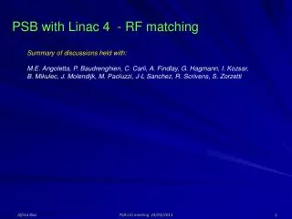
Review on the PSB with Linac 4 - rf aspects -. Beam loading in PSB cavities PSB transverse feedback requirements New PSB beam Control Synchronization with the Linac 4 Chopper. Beam Loading in PSB Cavities. M. Haase, A. Findlay, M. Paoluzzi, F. Pedersen .

E N D
Review on the PSB with Linac 4 - rf aspects - • Beam loading in PSB cavities • PSB transverse feedback requirements • New PSB beam Control • Synchronization with the Linac 4 Chopper Review on PSB with Linac 4 / rf aspects
Beam Loading in PSB Cavities M. Haase, A. Findlay, M. Paoluzzi, F. Pedersen • Requirements in terms of current From the rf cavity voltage feedback loops stand point the beam acts as a parasitic current which effect is cancelled in the ideal case so that the voltage remains as programmed The cavity amplifier needs to supply the current necessary to: Create the required voltage into the bare cavity Provide the accelerating energy … and also compensate the effect of loop errors Review on PSB with Linac 4 / rf aspects
Beam Loading in PSB Cavities • Requirements in terms of current C02: I0 for 8 kV = 3 APeak C04: I0 for 8 kV = 1 APeak I0 corresponds to the current required without beam and a perfectly tuned cavity. I0 also corresponds to the current requirement with any beam intensity when the tuning error and the stable phase are null (non-accelerated beam). Review on PSB with Linac 4 / rf aspects
Beam Loading in PSB Cavities Beam current For the following bunch with: Half sinus shape (extraction) Bunch length =TL 220 ns Total charges per bunch= 2 E13 The beam peak current is 22.8 A At the 1st harmonic : ÎH1 = 7.68 A At the 2nd harmonic: ÎH2 = 6.04 A Review on PSB with Linac 4 / rf aspects
Beam Loading in PSB Cavities C02 available current The C02 (h1) cavity tetrode can supply 24 Apeak which corresponds to 6 Apeak at the Gap. 3A are required in a ideal steady state situation (no error, no-acceleration). This leaves us with a 3 A overhead that can be used to accelerate the beam and compensate for possible tuning loop errors. The tuning loop bandwidth is in the order of 500 Hz when frequency transients or modulations can occur at a higher frequency. The maximum stable phase expected within the accelerating cycle is 22o (value taken from the present cycles which shouldn’t change much) . This corresponds to a greater Beam vector angle B as the accelerated bunch is asymmetric. B would be equal to S in a short bunch case; here as the bunch is longer, the h1 beam component is smaller but the same energy needs to be supplied => increase of the angle. S = 22o at 1 GeV results in a current requirement of 3.6 Apeak> 3Apeak! not including any potential tuning error effect. At 1 GeV the h1 current is 7.3Apeak with 2E13 ppb. The maximum allowed B is thus arcsin(3/7.3) = 24o. This corresponds to S < 18o. This is a very max value in the case of no tuning error Will the current limit be exceeded? => yes with the present accelerating cycle. Review on PSB with Linac 4 / rf aspects
Beam Loading in PSB Cavities C04 available current The C04 (h2) cavity tetrode-pair can supply 7 Apeak which corresponds to 3.5 Apeak at the Gap. 1A is required in a ideal steady state situation (no error, no-acceleration). This leaves us with a 2.5 A that can be used to accelerate the beam and compensate for possible tuning loop errors. The tuning loop bandwidth is in the order of 4 kHz when the frequency transients or modulation can occur at a higher frequency. The contribution of the h2 voltage to the acceleration of a dual harmonic beam has not been studied (by me at least) and should depend upon its amplitude and phase with respect to the h1 signal. For a pure h2 accelerating voltage, the power requirement should be the same as for h1 (same acceleration) and thus same current for the same voltage = 3.6 Apeak. Will the current limit be exceeded? May be not as long as the beam stays square enough! Yes if there is need for a 2 E13 beam accelerated on h2. Review on PSB with Linac 4 / rf aspects
Beam Loading in PSB Cavities Cavity current limit The main contributors to an extra-current demand are the accelerating energy ( = f(Bdot and IB) ) and the effect of tuning errors. The demand due to the acceleration can be fulfilled by lowering the maximum Bdot , may be at the price of a longer cycle ( and losses at low energy?) . The demand due to tuning errors can be fulfilled by limiting the transients (thus limiting the tuning errors) with a smoother behavior of the low-level beam control; target that should be reached with the new DSP based BC where the loop transfer functions can be programmed. Note that at injection, the beam transient corresponding to a parasitic error needs to be fully supplied by the amplifiers because it appears within the 100 us of the process, below the response time of the tuning loop Further MDs with the new beam control should help us evaluate the net effect with the L4 Beam. Review on PSB with Linac 4 / rf aspects
Beam Loading in PSB Cavities Loop stability effects Block diagram of the different loops involved in the Pedersen’s model Simplified Pedersen’s stability criteria in the context of short bunches, B = 0, L =0 and S small compared to cavity bandwidth. A,T,P are resp. the Amplitude, Tuner, Phase loop gain Pedersen’s model describing the beam control interaction in the context of an asymmetry of the cavity transfer function (the detuning being one cause of asymmetry) Review on PSB with Linac 4 / rf aspects
Beam Loading in PSB Cavities Loop stability effects The Pedersen’s model is valid for the fundamental modes in a single harmonic context. For a given Beam loading parameter (IB/I0), in a double harmonic context with different beam shapes, although it might be possible to compute a stable working point, it looks quite hazardous. The empirical method used until now was to lower the cavity impedance sensed by the beam by different means (Wide-Band Feedback, 1TFB) lowering as a result the equivalent IB/I0 In 2007 some MD’s have been carried-out to evaluate the stability threshold of the C04 cavity on the extraction plateau. In this experiment, the voltage of the second harmonic cavity (C04) has been lowered on a dual harmonic high intensity beam (lowering of I0 and as the bunch gets shorter, increase of IB) until the beam gets unstable. This operation (lowering of the h2 voltage) is classically required to match longitudinally PS and PSB. The result of the MD was that below VH2 = 1.67 kV (with VH1 = 8 kV), instabilities occur with 8E12 charges. A tempting extrapolation is to foresee a minimal VH2 = 1.67 x 2 / 0.8 (=beam intensity ratio) = 4.17 kV This approach is conservative as the beam signal drops when the h2 voltage is increased (cumulative effect) VH2 > 4 kV at the highest intensity (effect on PS matching?) Review on PSB with Linac 4 / rf aspects
Beam Loading in PSB Cavities Summary of the limiting factors The C02 is overloaded with the foreseen operation Solutions: upgrade the power amplifiers, minimize the max stable phase, minimize the LL loop transients with DSP BC The C04 should be used in a limited range of operations with the maximum intensity Solutions: upgrade the power amplifiers, minimize the max stable phase, minimize the LL loop transients with DSP BC, keep the bunch square (h1+h2 case only) VH2 > 4 kV at the highest intensity (H1+H2 context) Solution: Install a 1TFB or keep the bunches rectangular Review on PSB with Linac 4 / rf aspects
Transverse Feedback requirements • M. Chanel, A. Findlay, K. Hanke, G. Kotzian, B. Mikulec, D. Quatraro, G. Rumolo Introduction The present transverse feedback is “marginally” well dimensioned to keep all operational beams stable up to the maximum intensity ( 1013 charges per Ring). Losses are sometimes encountered at a maximum Beam intensity on the extraction plateau, most often on Ring 4 and rarely on Ring 1. These losses may be avoided by a fine setting of the synchronization loop and machine tune. Review on PSB with Linac 4 / rf aspects
Transverse Feedback requirements Present system • Two 100W amplifiers drive in Push-Pull opposite strip-line plates in the ring. • The vertical Plane TFB is not used, except for MDs • Although the system has been designed for a total bandwidth of 100 MHz, it is now covering a limited BW of 13 MHz. This was found to be sufficient and eases the setting-up of the system (less sensitive to loop delay errors). • With 200 W in the horizontal plane only, the system is well dimensioned for 1013 charges (just!) • Ageing low level system Review on PSB with Linac 4 / rf aspects
Transverse Feedback requirements Future system • If the parasitic field created by the beam current is proportional to the intensity, a doubling of the intensity means a doubling of the parasitic Field • A Doubling of the exciting field implies a doubling of the damping field • Doubling the kicker voltage mean multiplying by 4 the drive power • 400W amplifiers (and final matching resistors) instead of the present 100 W units would be marginally adequate. Review on PSB with Linac 4 / rf aspects
Transverse Feedback requirements Studies under way • Although the rule of thumb exposed in the previous slides can be considered as fair enough, some measurements were and are under way to characterize the transverse impedance. • Transverse imaginary impedance estimation by tune shift measurements: • Results: • In the vertical plane: 11 M/m total impedance at 160 MeV, and 4 M/m at 1 GeV • – Broadband, RW and Space charge combined effect – Same results in ring 2 and 4. • The Broadband only vertical impedance <<4 M/m. • In the horizontal plane, no measurable tune shift!? • Conclusion of these measurements: the Vertical impedance is in the expected ballpark and experience tends to prove that the vertical plane is not excited. • The absence of results in the horizontal plane is still a mystery as at least the space charge effect should have been measured (> 1/4th of the vertical tune shift expected considering the geometry of the chamber) (is the chromatic frequency to high where the beam spectrum is too low for a good S/N ratio?) Review on PSB with Linac 4 / rf aspects
Transverse Feedback requirements Resonance crossing The Transverse imaginary impedance estimation by tune shift measurements allows to calculate the RMS Resistive Wall and Space Charge impedance aroundξ.β/η = 37.4 MHz @ 160 MeV and 157 MHz at 1GeV This narrow band measurement intended for an estimation of wideband impedances doesn’t mean there are no other parasitic resonators outside this range and outside the particular spectrum of the beam during the measurements. Indeed, a maximum effect of transverse exciting fields is observed at two specific points during the accelerating cycle which leads to abrupt losses when the TFB is OFF. C478 C378 Review on PSB with Linac 4 / rf aspects
Transverse Feedback requirements Resonance crossing Review on PSB with Linac 4 / rf aspects
Transverse Feedback requirements Resonance crossing Review on PSB with Linac 4 / rf aspects
Transverse Feedback requirements Resonance crossing The previous images show that the beam is excited at very precise and reproducible instants in the cycle. These instants can be shifted in time by changing the value of the transverse tune. Is the instability due to the beam spectrum crossing a specific parasitic resonance? Is there one or more resonances? Where are they located? Some measurement were made to try answering these questions The results are not yet analyzed but the idea is explained below. Review on PSB with Linac 4 / rf aspects
Transverse Feedback requirements Resonance crossing frequency Betatron line 1st set of measurements Revolution line 2nd set of measurements Candidates time The FFT of the beam position is measured during a cycle with varying parameters (either the revolution frequency is varied or the tune value or both. The frequency value of all betatron lines when they start to appear is recorded. Doing that with different sets of values “might” spot the parasitic resonance(s). Review on PSB with Linac 4 / rf aspects
Transverse Feedback requirements Conclusion The present transverse feedback deals (marginally) with the 1 x 10¹³ ppb beam A power increase by a factor 4, for a beam current multiplied by 2, is a reasonable approach as long as there is no surprise. The surprise would come from a resonance that doesn’t show up with the present intensity and that would be located out the frequency range of the feedback loop. In such a pessimistic case this newly appearing resonance could be spotted in terms of frequency and then physically by deduction. A solution could then be applied at the source. N.B.: the low-level of the PSB TFB starts to age !! Review on PSB with Linac 4 / rf aspects
New PSB Beam Control • M.E. Angoletta, A. Findlay, F. Pedersen Status • A new DSP Based beam control of the same kind as the one used in LEIR has been successfully commissioned in Ring 4 with a low intensity beam (<200 E10 ppb). • The programmable loop transfer functions result in a qualitative improvement of the responses (synchro loop in particular) with respect to the present system using fixed parameters, set to a compromise value for all beams. • Further tests will be carried-out in 2009 with high intensities and control of the Blow-up signal. • Overall, major improvements are expected from the synchronization and second harmonic loop behavior with this new digital beam control. Review on PSB with Linac 4 / rf aspects
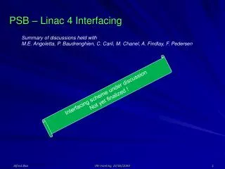
Chopper timing • M.E. Angoletta, P. Baudrenghien, C. Carli, A. Findlay, T. Fowler, F. Gerigk, A. Lombardi, M. Paoluzzi, F. Pedersen, L. Sermeus, R. Scrivens Introduction • In the present injection scheme at 50 MeV, the entireLinac 2 beam pulse reaches the PSB equipments; the destination selected by a distributor is either a dump, a ring or the in-between-two-rings space during the 80 ns rise time of the distributor. • The increase of the incoming beam energy to 160 MeV will have a negative impact on the radio activation of the targeted elements, effect amplified by the foreseen increase of the distributor rise time and the proposed injection scheme at full rf voltage that doesn’t allow the full capture of a continuousLinac beam. Review on PSB with Linac 4 / rf aspects
Chopper timing Most constraint full operation: the longitudinal painting h1 Bucket limits h2 Buckets limits ΔT1 = f(ΔE, φS , V1, V2) ΔT2 = f(ΔE, φS , V1, V2) ΔT3 = f(ΔE, φS , V1, V2) ΔT4 = f(ΔE, φS , V1, V2) 4 timing values should be supplied for each injected turn Beam Revolution reference tics Review on PSB with Linac 4 / rf aspects
Chopper timing Equipment to be synchronized Pre-chopper +LEBT Debuncher RF Feedforward Source Distri 4*rf 180 m 45 keV Chopper Amplitude modulated for energy modulation (painting) • RF feedforward, energy modulator, debuncher, distributor and rf have to be in phase with the Chopper Review on PSB with Linac 4 / rf aspects
Chopper timing Ring switching Ring X-1 Distributor field Ring X Chopping during one period to maintain rf synchronism T > 1 us -> too long Revolution Reference All rings cannot be kept in phase at injection due to the chopper BEAM-OFF duration limited to 1μs => different phase in each ring The dephasing will be chosen as a 1/10th of the revolution multiple to adapt to the present philosophy allowing injecting multiples of a 1/10th revolution. Review on PSB with Linac 4 / rf aspects
Chopper timing Injection scheme • The idea is to inject the beam on a ramping PSB field (1.2 T/s instead of 0.4 T/s presently). This would allow a shorter stay where space charge is critical at low fREV. • It is not decided yet what injection scheme to choose. • 2 scenari will be compared here. • 1st scenario: Injection at a fixed frequency as it is the case with Linac 2 • 2nd scenario: Injection in an accelerating bucket Review on PSB with Linac 4 / rf aspects
Chopper timing Injection scheme • The longest injection will take 100 μs in each ring • The field increase will be 1.2 G/100μs • This means Δp = 120 keV/100 μs if following the ΔR =0 accelerating law (bucket height = 2.5 MeV). This increase of momentum corresponds to a shift in energy of the accelerating bucket. • This means ΔR = -0.8 mm/100 μs if following the Δp = 0 frequency law. This is the radial steering error that will be obtained if injecting at a fixed energy. • This means Δp = -7.5 keV/100 μs and ΔR = -0.86 mm/100 μs if following the Δf = 0 • This decrease of momentum corresponds to a shift in energy of the decelerating bucket. Review on PSB with Linac 4 / rf aspects
Chopper timing Injection scheme with a complete field compensation and fixed rf frequency • The field increase will be 1.2 G/100μs… • … but if needed this field increase can be temporarily compensated for by the BdLcorrection elements - and not only as an offset -> it can be programmed to compensate the increase of the main field with a GFAS • The advantage of such a total field increase compensation is that you can inject at a fixed energy and a fixed frequency in all rings and stay at ΔR =0. • The price to pay is that it requires an energy catching-up of up to 127 x 4 = 508 keVfor the last ring. Review on PSB with Linac 4 / rf aspects
Chopper timing Injection scheme with a complete field compensation and fixed rf frequency Pre-chopper +LEBT Debuncher Source Distri 4*rf 180 m 45 keV To Linacrf feed-forward Chopper ON/OFF Injection Sequencing control Voltage modulation Phase modulation Number of turns + VH1 BIXi.SDIS Rf for synchro, 4 rings, h1 or h2 Linacrf Fixed Injection reference source Rev + 10* REV BIX. SINJ ΔE 4 rings Application 4 timing values foreach injected turn Review on PSB with Linac 4 / rf aspects
Chopper timing Injection scheme with an offset field compensation and accelerating bucket • Here the field increase is only compensated as an offset so that the first injected turn senses the same field in each ring. The Field increase though is preserved and the frequency can follow the ΔR=0 accelerating law. • As for the total field correction, there is also an energy catching-up process to undergo after the injection when canceling the BdL correction. • The energy catching-up value is 0 keV for the first injected ring and 360 keVfor the last ring. • This value is to be compared to the max 508 keVrequired to catch-up with a single fixed frequency injection. Review on PSB with Linac 4 / rf aspects
Chopper timing Injection scheme with an offset field compensation and accelerating bucket • Here all rings would be synchronized to a single reference before injection. From a start point they all get a specified frequency/phase offset and all rf sources start a ΔR=0 frequency ramping. The injection starts at the same instant. All the phase advances are pre-calculated so that, at the switching from one ring to the following, the buckets are at the expected position. • In this context the chopper timing circuit can still receive a single reference signal – being the rf of the last injected ring - because, although the frequencies are different from ring to ring all phase values are predictable. The choice of the last ring is due to the fact that as soon as one ring ends its injection, the phase loop is closed and the phases cannot be predicted anymore. • Concerning the Linac energy, it would ramp-up each turn by Δp = 120 keV/100 μs to follow the accelerating bucket and should step down during the switching time to the following ring (Distributor rise time < 500 ns!!!) If we don’t compensate the magnetic field we don’t need this stepping of the linac energy, but the price will be -3.4 mm in the last ring and a total linac energy ramping of 480 keV on which is superimposed the painting. Review on PSB with Linac 4 / rf aspects
Chopper timing • Injection scheme with an offset field compensation • and accelerating bucket Pre-chopper +LEBT Debuncher Source Distri 4*rf 180 m 45 keV To Linacrf feed-forward Chopper ON/OFF Injection Sequencing control Voltage modulation Phase modulation Number of turns + VH1 BIXi.SDIS Rev R1 Linacrf Fixed Injection reference source BIX. SINJ ΔE 4 rings Application 4 timing values foreach injected turn Review on PSB with Linac 4 / rf aspects
Chopper timing • Injection in a Stationary Bucket - Summary Review on PSB with Linac 4 / rf aspects
Chopper timing • Injection in an Accelerating Bucket - Summary Review on PSB with Linac 4 / rf aspects
Chopper timing • Injection at Δp = 0 and BdL too slow to compensate the Main field increase- Summary Review on PSB with Linac 4 / rf aspects
Review on the PSB with Linac 4 - rf aspects - Conclusion • Beam loading in PSB cavities • The C02 cavity will be overloaded with the present Bdot at the highest intensity. • Same problem with C04 in case of a pure h2 acceleration at the maximum intensity. • For stability reasons Vh2 should not be lowered below 4 kV in a dual harmonic mode at extraction • PSB transverse feedback requirements • The power equipment needs to be upgraded to 1 kW (400 W + margin) instead of 100W presently. • The low level should be renewed (option) • New PSB beam Control • Required for the job. An injection synchronization scheme should be implemented (plug-ins and some • software to add). A synchrotron even mode damping system could be foreseen in the context of sharp edges in • the longitudinal density (no Landau damping). • Synchronization with the Linac 4 Chopper • Injection scheme to be chosen and new circuit to develop, together with an application program. Review on PSB with Linac 4 / rf aspects