Download
1 / 20
200 likes | 208 Views
This document outlines the baseline scope, cost, schedule, and staffing of the Linac and RF systems for the NSLS-II Project. It provides updates on technical progress, cost and schedule performance, risks, and lessons learned. It also includes details on the RF systems in the storage ring and linac, as well as the storage ring cavities and the development of the cavity controller.

E N D
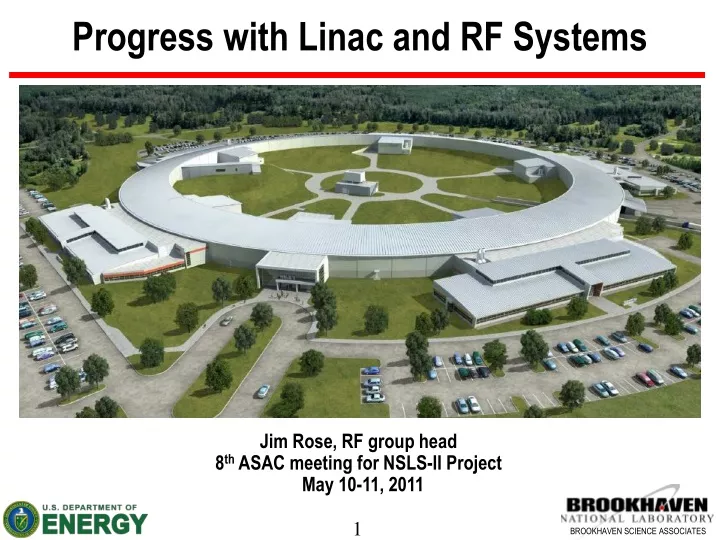
Progress with Linac and RF Systems Jim Rose, RF group head 8th ASAC meeting for NSLS-II Project May 10-11, 2011
Outline Baseline Scope, Cost, Schedule & Staffing Progress since last ASAC meeting Technical Progress Cost & Schedule Performance Risks & Lessons Learned Conclusions
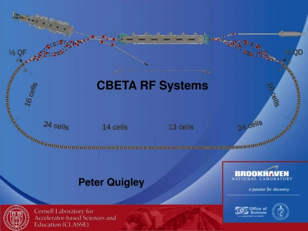
NSLS-II RF Systems Storage Ring: Two ~9m RF straights each with two 500 MHz SRF cavities and one 1500 MHz passive bunch lengthening cavity Only one RF straight in initial operations 3 GeV booster with one 7-cell cavity powered by 80 kW IOT amplifier 200 MeV linac with four 5.2 m TW structures powered by two 42 MW klystrons with SS modulators and third “hot spare” RF building housing two 300 kW klystron amplifiers Also houses 850 W LHe refrigerator Future expansion for another 2 RF systems
Linac RF Systems • 200 MeV S-band linac: 15 nC/pulse requires beam loading compensation using a feedforward algorithm in the cavity field controller • 500 MHz modulated gun with 500 MHz buncher, 3 GHz pre-buncher, 3 GHz TW buncher and four 5.2m TW structures • Two 42MW klystrons with Solid State Modulators using IGBT switches on multiple- primary, split-core pulse transformer • Third “Hot Spare” klystron can be switched to either position
Linac • Linac beam line component production well along: • TW structure couplers complete • TW braze stacks complete, waiting to solder cooling channels- an improvement over previous glued channels • Sub-harmonic and Pre-buncher complete • Solenoid coils complete, triplets(?) • Linac front end delayed 3 months but overall schedule ahead by 2 months
Linac: Thales TH2100 klystron TH2100B- 2.998 GHz42 MW klystron 50 Hz rep rate First Linac klystron completed at factory, klystrons 2 and 3 to be ready for FAT in June- Will perform site visit to Thales in Villezy to witness tests
Linac: Scandinova Modulators Construction of all three modulators in progress, 1st unit ready for test mid May. Modifications made in response to PSI workshop including wire lugs replacing push-on connectors, improved mechanical design, fixed filament current read back, klystron low impedance ground connection
Storage Ring Transmitter- Klystrons Two TH2161B-3 klystrons in production, FAT in conjunction with Linac klystrons in June
Storage Ring Transmitter: 540 kVA Cathode supplies in production 3-phase delta-Y HV transformers PSM solid state switcher power supply includes improved output filtering, higher and variable switching frequency as a result of NSLS-II LLRF tests at CLS
Storage Ring Cavities • Cavity redesigned for larger coupling: Qext = 65000 • Original HFSS analysis repeated with Microwave Studio (insert Murali slide next) • Niobium cavity redesigned for ASME pressure vessel code: niobium thickness increased in fluted beam tube, waveguide • Cavity MAWP increased from 1.49 to 1.55 bar to accommodate pressure drop from cryomodule to He compressor suction return line.
Storage Ring Cavities • Contract award April 12th to AES for 2 turn-key cavity cryomodule systems • Meyer tool subcontracted to build cryomodule- built 6 prior for Cornell, CLS, TLS • AES has excellent track record for ILC niobium cavity production- • Risk in cryomodule assembly in clean room: first time for AES: Close proximity will allow frequent review, placement of NSLS-II technician on site
Storage Ring Helium Cryo-System • Cryogenic System contract award to LINDE • Turn key system to include: • 850 W Cold Box and 3500 L dewar • 250 kW Kaeser compressor with 2nd as redundant spare • 75 kW backup compressor- air cooled in the event of power failure • Medium pressure gaseous Helium storage • Valve box • All warm and cold piping • Installation, commissioning and acceptance test on site
RF Cryogenic System: Dedicated 850 W Helium refrigerator and LN2 +/- 2 mbar LHe +/- 50 mbar LN2 For frequency stability Dedicated LN2 distribution for RF Gaseous Helium tank farm with recovery compressor Cold box, 3000-l Dewar on RF building mezzanine Compressor building decoupled from tunnel SRF Cavities in tunnel Valve boxes on tunnel roof
Successful Development of Cavity Controller • Digital Field Controller • 50 MHz IF • Tested at CLS on hardware nearly identical to NSLS-II: 300 kW klystron and CESR-B SRF cavity • Meets NSLS-II field spec. of 0.15 degree and 0.05% H. Ma CLS Analog A=0.073%rms φ=0.12° rms NSLS-II A=0.026%rms φ=0.02°rms CLS tests courtesy M. de Jong
Preliminary tests of LLRF at CLS CLS Analog LLRF feedback Normal Ops NSLS-II Digital LLRF feedback Machine Studies
NSLS-II 3rd Harmonic Cavity Coupled-two cell cavity allows 1 MV in compact cryomodule with external tuner and small heat leaks however it requires care in controlling the 0 andπ-mode frequency separation to avoid exciting the 0-mode π-mode 0-mode Δ(0- π) fixed by coupling Excitation of π-mode by RF 3rd harmonic 0-mode not excited Parked Tuning Fixture 3xRF –(n+1)Frev 3xRF –nFrev 3xRF Two 2-cell cavities Frev~380kHz Cryomodule is complete and initial cold-test conducted verifying the frequency tuning over a 1 MHz band while keeping 0 and π mode frequency separation constant to within 10 %.
Landau Cavity: cryomodule complete First horizontal cold test complete completely validates 0-π mode tuning over 1 MHz bandwidth. Low Q loaded (6e7 vs. 2e8) explained by trapped TE mode. Need to design and fabricate ferrite dampers, tuner mechanism
Conclusion • All major procurements awarded and vendor fab in progress • First systems delivery well ahead of required dates • SR transmitter in August • Linac in September • BR transmitter in October • Long lead items (SRF cavities, Cryosystem) fit within schedule • Early success with 3rd Harmonic SRF cavity • System performance demonstrated at Canadian Light Source with NSLS-II digital cavity controller, nearly identical transmitter-cavity system
Acknowledgements This work was performed by and under the guidance of Alexei Blednykh, John Cupolo, Ray Fliller, Bill Gash, Feng Gao, B. Holub,Y. Kawashima, Hengjie Ma, Andy Marone, Bob Meier, Payman Mortazavi, George Mulholland, Jorge Oliva, Satoshi Ozaki, Ed Quimby, Jim Rose, Timur Shaftan, Bob Sikora, Nathan Towne, Ernst Weihereter, Ferdinand Willeke and Takeshi Yanagisawa as well as the support of the entire NSLS-II team. We would also like to thank the SCRF groups at Cornell, KEK, CLS, TPS and DLS for their continuing help and encouragement, in particular Hasan Padamsee, Sergie Belomestnykh, Valery Shemelin, Takaaki Furuya, Mark de Jong, Chaoen Wang and Morten Jensen We would like to acknowledge the excellent work by Niowave Inc. in the fabrication of the 3 HC under the DOE SBIR