Download
1 / 20
200 likes | 287 Views
Detailed information on PSB injection sequencing in Linac 4 era, discussing beam modulation, chopper timing, and distributor selection in the new system.

E N D
PSB Injection Sequencingin the Linac 4 Era Synthesized information from: M.E. Angoletta, P. Baudrenghien, C. Carli, A. Findlay, T. Fowler, F. Gerigk, A. Lombardi, M. Paoluzzi, F. Pedersen, L. Sermeus, R. Scrivens PSB Injection Sequencing in the Linac 4 era Alfred BLAS
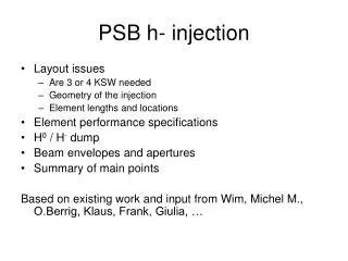
The Linac 4 H- beam is injected in the PSB at 160 MeV/c (v=157mm/ns) instead of 50 MeV/c with Linac 2 H+. Radio-activation of the PSB can be limited by chopping the beam at 3 MeV/c during “dead times” of the multi-turn injection process. • “Dead times” of the multi-turn injection process means: • Switching time from one ring to the following (distributor rise time 500 ns) • Out-of-bucket beam injection Outline PSB Injection Sequencing in the Linac 4 era Alfred BLAS
Pre-chopper from RF Structures for Linac 4, F. Gerigk, PAC 07 Source LEBT Distri 4*rf 180 m 45 keV Chopper Amplitude modulated for energy modulation (painting) from P. Baudrenghien Linac 4 beam from the source PSB Injection Sequencing in the Linac 4 era Alfred BLAS
The beam out of the source is chopped by a pre-chopper until it stabilizes (< 1ms). • When this is achieved the beam flies through a LEBT which requires 20 μs to let through the full intensity (space charge compensation). • The beam is then accelerated in the RFQ after which the fast chopper selects the destination: either distributor at the end of the Linac or the 3 MeV dump. This dump position can only be hold for 1 μs. • Just before the distributor the beam flies through the last two PIMS cells where the voltage can be modulated. This modulates the beam energy and the beam flight time towards the PSB. • The beam then flies through the distributor which selects its final destination in always the same sequence from Head dump to Tail dump via the 4 PSB rings from ring 4 to ring 1 (top-down). The Linac-to-ring distance varies depending on the selected ring. Beam generation PSB Injection Sequencing in the Linac 4 era Alfred BLAS
The distributor selects the destination of the Linac beam into the PSB. 5 positions selected by 5 magnets that are adding up their field Rest position = head dump no kick 1st position = ring 4 1st magnet fired 2nd position = ring 3 1st + 2nd magnets fired 3rd position = ring 2 1st + 2nd + 3rd magnets fired 4th position = ring 1 1st + 2nd + 3rd +4th magnets fired 5th position = Tail dump 1st + 2nd + 3rd + 4th + 5th magnets fired These 5 magnets should stay active until the end of the Linac pulse (total length 450 μs, see slide 8) Elements affecting the Chopper timing 1 – The distributor (source T. Fowler, L. Sermeus) The beam travel time within the injection channels is different from ring to ring and this affects the beam-to-bucket synchronization Kicker rise time (10-90%) = 500 ns Estimated value with solid state switches; Could be diminished to 200 ns with thyratrons More information in June 2009 PSB Injection Sequencing in the Linac 4 era Alfred BLAS
The rf amplitude is modulated to modulate the beam output energy (bucket painting) . • From the central 160 MeV/c , an extra ΔE from -1.2 MeV to +1.2 MeV is added. • For each cell, this means a Klystron power ranging from 0.51 MW to 0.84 MW (>1.25 MW available) • The amplitude change rate is limited by the klystron’s power. • For ΔE a single sweep from -1.2 MeV to +1.2 the required time is 8.7 us for 1MW available • For a lower ΔE the sweep time can be decreased proportionnaly (4.35 us from -0.6 to +0.6MeV) • Energy modulation means beam flight time modulation : +/- 3.4 ns difference over the 180 m separating PIMS and PSB injection Foil (source A. Lombardi) • This will affect the beam phasing with respect to the debuncher and to the rf buckets. Elements affecting the Chopper timing 2 – Last 2 PIMS cells (source F. Gerigk) PSB Injection Sequencing in the Linac 4 era Alfred BLAS
Trise/fall < 3.6 ns • 25 ns < TON < 1000 ns • TOFF > 40 ns • Values to be checked with the new version of the amplifier to be tested in January 2009 • The reproducibility of the response time from trigger to kick remains a question mark • Linac bunch length out of the RFQ 280 ps The Chopper (source M. Paoluzzi) Chopper IN/OUT PSB Injection Sequencing in the Linac 4 era Alfred BLAS
Pre-chopper Upstream the RFQ at 45 keV/c • Trise < 1ms • Tfall< 2μs • Tstable> 1 ms • After Tfall, the beam starts to feed the downstream LEBT (beam transport) which requires 20 us to stabilize (space charge compensation) and deliver the full current • “The pre-chopper is used once per cycle; it doesn’t act at the end of the cycle” “the beam OFF duration is not unlimited” The (slow) pre-Chopper (source Richard Scrivens) The beam into RFQ rise time is more likely around 20 μs PSB Injection Sequencing in the Linac 4 era Alfred BLAS
Bucket Painting (source C. Carli) Beam Revolution reference tics PSB Injection Sequencing in the Linac 4 era Alfred BLAS
Injection from the 1st turn into R4 until the last turn into R1 can last 401 μs (4 x 100 turns/ring + 3 x 500 ns distributor rise time) • Such an injection duration associated with a non-zero Bdot leads to an horizontal injection error if the Linac energy remain constant and if the field in each ring is not compensated for. • For Bdot = 0.1 T/s, the field increase during 400 μs will be 0.4 Gauss or 4 tics of the 0.1 Gauss B-train. • With dp=0 => and (dp = 0 frequency law followed by the rf) • ( BINJ 160MeV = 2311 G R = 25 m p = 570 MeV/c ΔE [eV] = 0.519. Δp[eV/s] . c) • => withBdot = 0.1T/s and the maximum number of turns =>ΔR= -0.26 mm. • This corresponds to a 1 mm error for a presently typical 0.4 T/s at injection with a total ΔB = 1.6 Gauss . • If we can increase the Linac energy by Δp such that dp/p = dB/B in order to have ΔR = 0 • we would need Δp = 0.11 MeV for ΔB = 1.6 Gauss, and the frequency law should be adapted accordingly. Consequences of the B field increase during injection PSB Injection Sequencing in the Linac 4 era Alfred BLAS
If B (0.4 T/s) R (-1mm for 100 turns in each ring) and frequency law = • If B (0.4 T/s) and p (0.11 MeV) ΔR = 0 and frequency law = • In both cases with ΔB = 1.6 Gauss, the revolution frequency swing would in the order of 700 Hz Consequences of the B field increase during injection PSB Injection Sequencing in the Linac 4 era Alfred BLAS
The injection can be made in different ways: • One fact is accepted: the field will increase during injection. • If we want the same conditions in each ring, we need to apply a Field compensation with the Bdl magnets. What is the possible amplitude of this correction? • Would we like to make the injection at a fixed frequency? Can we make a B-field correction with a slope that compensates the one of the main magnets? • With the B-field compensation, the conditions are identical during the injection but are different from one ring to the other during the catch-up process that follows. • One different approach is to play with the linac energy. The beam energy is increased at a rate that corresponds to the Field increase ΔR=0 and so is the rf. We need to check what the head room is in term of energy increase??? • One practical aspect is that having a single rf reference would ease the synchronization of all the linac 4 and PSB elements. • Do we accelerate during injection or do we not? • If we don’t: • If all rings are synchronized to a single reference following a Δp=0 law, the price to pay will be a radial offset (1 mm max for 0.4 T/s) • If we don’t want this radial offset, we can increase the Linac energy at the same rate as B (0.11 MeV max in the most demanding case with 0.4 T/s). The single rf reference will follow this time a different frequency law • If we don’t want to increase the Linac energy, we can compensate the field in each ring (max 1.6 Gauss with 0.4 T/s) using the Bdl correction. A single rf reference can be applied but it should stay at a fixed value! • If we do: • Each ring has its specific rf following a ΔR=0 law, The proper inter ring rf phasing during ring switching can be pre-established from initial conditions with initial phases and frequencies being set at a specific time, and from then on, the sequence is programmed (we don’t follow the measured Btrain ) Injection scenari (under construction!!) PSB Injection Sequencing in the Linac 4 era Alfred BLAS
VH1 VH2 Stable φ REV ref Distri. Position Linac Energy offset Distributor trig Bucket Shape Window generation+ Gating Chopper ON/OFF Bucket Position RF Feed- Forward Information flow-chart • The distributor position impacts the beam flight distance • The energy offset impacts the beam flight time and the bucket boundaries PSB Injection Sequencing in the Linac 4 era Alfred BLAS
Rev. reference h1 Bucket limits h2 Buckets limits ΔT1 = f(ring selected) ΔT2 = f(ΔE, φS , V1, V2) ΔT3 = f(ΔE, φS , V1, V2) ΔT4 = f(ΔE, φS , V1, V2) ΔT5 = f(ΔE, φS , V1, V2) Bucket Painting • The chopper ON/OFF control would require revolution tics synchronous with the rf buckets + 5 timing values for each turn in each ring. These values are calculated at an application level and sent to a hardware register for each cycle (ppm). PSB Injection Sequencing in the Linac 4 era Alfred BLAS
Ring X-1 Distributor field Ring X Chopping during one period to maintain rf synchronism T > 1 us -> too long Revolution Reference Chopping during change of injected ring 1. All rings in rf phase This approach with all rings synchronized on the same signal is not viable It requires too long a chopping time for the actual circuit capability PSB Injection Sequencing in the Linac 4 era Alfred BLAS
Chopping during change of injected ring 1. Rf phase different from one ring to another Ring X reference Distributor field Ring X-1 Ring X Ring X-1 reference Force Chopper-ON + change Chopper REV ref Chopping OFF With the REV reference signal delayed by 500 ns or 5/10th of a turn (distributor rise time = 500 ns) for the rings in descending order, the chopping will be limited in time according to the specifications NB: the diagram is valid for a whole number of turns injected in ringX . If additional 1/10th of a turn are required, the REV reference of the following ring should be delayed accordingly!!! PSB Injection Sequencing in the Linac 4 era Alfred BLAS
Revolution signal delayed by some 1/10th of a period with respect to the previous ring. The first 5/10th comes for the distr. Delay and the other 1 to 9/10th for the decimal part of the nb of turns in the previous ring Chopper ON (high) – OFF (low) {high => no beam to PSB} Number of turns & VPROG H1 To Chopper Control 5/10th of TREV = Distr. Rise time Rev PSB Inj. REF Source LL RF Rev R4 Rev R3 RevR2 RevR1 SDis represented for 1.0 turn injected in Ring 4 1.5 turn in Ring 3 1.0 turn in Ring 2 0.1 turn in Ring 1 10*Rev SDis R4 SDis R3 SDisR2 SDisR1 SDisTail Rev signals follow a Δp = 0 law during injection NOT ΔR = 0 !!!! To Distr. and Chopper Control Reference signals rf R4 rf R3 rf R2 rf R1 BIX. SINJ To rfsynchro = h1 (or h2 if VPROG H1 = 0) NB: All signals in phase with 10*Rev OK for counters!! Linacrf To chop in synchronism with the bunches PSB Injection Sequencing in the Linac 4 era Alfred BLAS
5 timing values foreach injected turn Rev R4 Rev R3 RevR2 RevR1 Chopper and Energy Modulator Control Analog modulation PIMS ΔE SDis R4 SDis R3 SDisR2 SDisR1 SDisTail Chopper ON/OFF To Chopper and RF feed-forward Chopper Control ΔE R4 ΔE R3 ΔE R2 ΔE R1 PIMS voltage modulation PSB Injection Sequencing in the Linac 4 era Alfred BLAS
5 timing values foreach injected turn Number of turns & VPROG H1 PSB Inj. REF Source Chopper and Energy Modulator Control Rev LL RF Analog modulation PIMS ΔV 10*Rev Chopper ON/OFF To Chopper and RF feed-forward BIX. SINJ Chopper Control Linacrf Rfsynchro 4 rings SDIS 4 rings ΔE 4 rings PSB Injection Sequencing in the Linac 4 era Alfred BLAS
Pre-chopper Source LEBT Distri 4*rf 180 m 45 keV To Linacrf feed-forward Chopper ON/OFF Injection Sequencing control Voltage modulation BIXi.SDIS Number of turns + VH1 Rf for synchro, 4 rings Injection sequencing - Possible setup Rev + 10* REV Linacrf Dedicated Injection rf source in BOR BIX. SINJ ΔE 4 rings 5 timing values foreach injected turn Could be a programmable fixed frequency source at the ISC level Application PSB Injection Sequencing in the Linac 4 era Alfred BLAS