Download
1 / 13
130 likes | 251 Views
Review on shorter PSB main bending magnets. Injection layout with short magnets Advantages & Disadvantages Wim Weterings 21-06-2012. Current Baseline Layout. Issues in the Current Baseline Layout.

E N D
Review on shorter PSB main bending magnets Injection layout with short magnets Advantages & Disadvantages Wim Weterings 21-06-2012
Issues in the Current Baseline Layout The diameter of the injection chamber is reduced by 6mm in order to create space for the septum. This results in reduced aperture for the injected beam The available space for the septum magnet between the two adjacent chambers is only 13mm The limited space forces to have an internal dump with instrumentation all inside BSW4 At the entrance of the H-/0 dump there is still overlap between the H0 beam and painted beam envelope which can result in beam losses on the dump • The available space between BSW2-3 for the stripping foil unit is 148mm resulting in a limited stripping foil and beam screen space of ~120mm. • Injected beam 10mm offset inside injection chamber The BSW1 and BSW4 magnets are in the fringe field of the main dipoles. Simulations have shown that only a small reduction of ∫B.dl of BSW1 occurs (~3‰). Nevertheless, it is not excluded that the BSW1 will have Impact of on the main BHZ dipoles magnetic field.
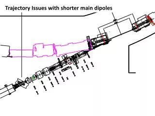
Proposed Layout500mm increased injection straight - shorter MB162 and MB011 dipoles
Advantages Proposed Layout 500mm increased injection straight - shorter MB162 and MB011 dipoles The possibility is created to have an external dump The available space for the septum magnet can be increased to ~20mm No more aperture restrictionsfor the injected beam • Injected beam can be centered inside injection chamber At the entrance of the H-/0 dump there is no more overlap between the H0 beam and painted beam envelope thus reduced risk of beam losses on the dump Sufficient space is created to have vacuum sector valves for each ring The available space between BSW2-3 for the stripping foil unit could be increased by ~15mm. Sufficient space is created to have vacuum sector valves for each ring The BSW1 and BSW4 magnets would be further away from the fringe field of the main dipoles.
Vacuum Sector Valves OptionsCurrent proposal Expensive and Bulky valves, integration difficulties Only space for 1 Ion-Pump only on stripping foil unit or manifold
Vacuum Sector Valves Options 500mm increased injection straight proposal Space for dedicated manifold equipped with multiple Ion-Pumps (and maybe instrumentation) As a reminder; Dedicated space for a shielded external dump Dedicated space for sector valves Dedicated space for sector valves
Integration Issues Current design creates a very crowded area !
Integration Issues Support structures have not been studied yet • 500mm additional space would facilitate integration of not yet shown elements: • Support Structure • Bus-Bars • Cabling • Power Transformers • etc.
Layout ImplicationsCurrent Situation 2654 Dimension “A”
Layout Implications 500mm increased injection straight proposal 2654 + 500 Dimension “A” - 34.5mm shift
Layout Implications Option for 34.5mm shifted injection line No direct interference due to shifted beam line DHZ 70 DHZ 50 Possible to use DHZ 50 & DHZ 70 for 34.5mm offset (34.5mm / 3m -> ~11.5mrad deflection)
Summary • No more aperture restriction. • Increased space for septum to ~20mm. • Tight space between BSW2 & 3 for the stripping foil unit improved. • No more scraping of beam envelope on H-/0 dump. • Shielded external dump. • Small vacuum sector valves for each ring. • BSW1 & 4 further away from BHZ fringe field. But • Introduction of new type of main dipole. • PSB lattice perturbation. • Shifted injection line needed. • Additional requirements for DHZ 50 & DHZ 70 to create a 34.5mm offset.