Download
1 / 21
240 likes | 843 Views
Multi-Cycle MIPS Implementation. Ellen Spertus MCS 111 November 4, 2003. Single-cycle Each instruction takes one clock cycle. There is one set of control signals for each instruction . The clock period is the length of the slowest instruction. Multi-cycle

E N D
Multi-Cycle MIPS Implementation Ellen Spertus MCS 111 November 4, 2003
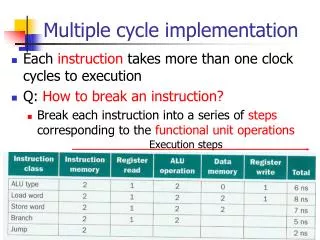
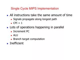
Single-cycle Each instruction takes one clock cycle. There is one set of control signalsfor each instruction. The clock period is the length of the slowest instruction. Multi-cycle Each instruction takes multiple clock cycles. There is one set of control signals for each cycle of each instruction. The clock period is the length of the slowest stage. Comparison
Sample program Assembly code: top: add $r1, $r2, $r3 sw $r5, 0x3000($r2) beq $r2, $r5, end j top end: Machine code: 4000: add $r1, $r2, $r3 4004: sw $r5, 0x3000($r2) 4008: beq $r2, $r5, _____ 400C: j ____
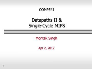
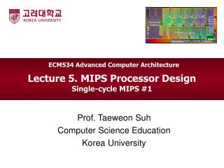
add$r1, $r2, $r3 2 3 1 Multi-cycle datapath
How to produce control bits? • Single-cycle • Input: opcode bits • Output: control bits • Multi-cycle • Input: opcode bits, cycle • Output: control bits (I dropped op5, op4, and op3 because they’re not needed for the MIPS subset we’re examining.)
sw$r5, 0x3000($r2) 2 5 3000
Big picture • Can we add a counter that keeps track of what cycle we’re on? • Can we come up with a boolean function to convert from (opcode, cycle) to control bits? • Consequence:
beq$r2, $r5,-3 2 5 3000
j0x4000 1000
Details I ignored • We actually need 5 cycles (and __ bits to represent them) for load-word. • I didn’t always show the value of deasserted signals (such as RegWrite). • To simplify logic, the second cycle always computes the branch target address, even if it is not needed (e.g., for r-type instructions).
Actual implementation • While a giant truth table like I described would work, that’s not how it’s done in practice. • The book describes using a finite state automaton (although that’s not very efficient either). • The actual implementation is with microcode.
Alternative: microcode • Each microinstruction consists of a set of control signals • Every machine instruction (e.g., ) leads to the execution of several microinstructions
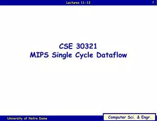
Microcode controller (fig. 5.47) M i c r o c o d e s t o r a g e D a t a p a t h c o n t r o l O u t p u t s o u t p u t s I n p u t 1 S e q u e n c i n g M i c r o p r o g r a m c o u n t e r c o n t r o l A d d e r A d d r e s s s e l e c t l o g i c I n p u t s f r o m i n s t r u c t i o n r e g i s t e r o p c o d e f i e l d
Levels of instructions • MIPS assembly language instructions • Written by assembly language programmer • Example: • MIPS machine language instructions • Created by assembler • Example: • MIPS microinstruction • Created by architect • Example: