Download

1 / 46
470 likes | 666 Views
Sequential logic. Sequential circuits simple circuits with feedback latches edge-triggered flip-flops Timing methodologies cascading flip-flops for proper operation clock skew Asynchronous inputs metastability and synchronization Basic registers shift registers. Sequential circuits.

E N D
Sequential logic • Sequential circuits • simple circuits with feedback • latches • edge-triggered flip-flops • Timing methodologies • cascading flip-flops for proper operation • clock skew • Asynchronous inputs • metastability and synchronization • Basic registers • shift registers CSE 370 - Winter 2000 - Sequential Logic - 1
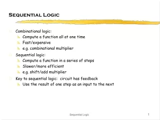
Sequential circuits • Circuits with feedback • outputs = f(inputs, past inputs, past outputs) • basis for building "memory" into logic circuits • door combination lock is an example of a sequential circuit • state is memory • state is an "output" and an "input" to combinational logic • combination storage elements are also memory new equal reset value C1 C2 C3 mux control comb. logic multiplexer clock state comparator equal open/closed CSE 370 - Winter 2000 - Sequential Logic - 2
Circuits with feedback • How to control feedback? • what stops values from cycling around endlessly X1X2•••Xn Z1Z2•••Zn switchingnetwork CSE 370 - Winter 2000 - Sequential Logic - 3
"1" "stored value" "0" "remember" "load" "stored value" "data" Simplest circuits with feedback • Two inverters form a static memory cell • will hold value as long as it has power applied • How to get a new value into the memory cell? • selectively break feedback path • load new value into cell CSE 370 - Winter 2000 - Sequential Logic - 4
Q R S R Q Q' S Q S' S' R' Q Q' R' Memory with cross-coupled gates • Cross-coupled NOR gates • similar to inverter pair, with capability to force output to 0 (reset=1) or 1 (set=1) • Cross-coupled NAND gates • similar to inverter pair, with capability to force output to 0 (reset=0) or 1 (set=0) CSE 370 - Winter 2000 - Sequential Logic - 5
R Q Q' S Timing behavior Hold Race Reset Set Reset Set 100 R S Q \Q CSE 370 - Winter 2000 - Sequential Logic - 6
S R Q0 0 hold0 1 01 0 11 1 unstable Q Q'0 1 Q Q'1 0 Q Q'0 0 Q Q'1 1 State behavior or R-S latch • Truth table of R-S latch behavior CSE 370 - Winter 2000 - Sequential Logic - 7
SR=10 SR=00 SR=01 SR=00 SR=10 SR=01 Q Q'0 1 Q Q'1 0 SR=01 SR=10 SR=11 Q Q'0 0 SR=11 SR=11 SR=00 SR=11 SR=00 SR=01 SR=10 possible oscillationbetween states 00 and 11 Q Q'1 1 Theoretical R-S latch behavior • State diagram • states: possible values • transitions: changesbased on inputs CSE 370 - Winter 2000 - Sequential Logic - 8
SR=10 SR=00 SR=01 SR=00 SR=10 SR=01 SR=01 SR=10 SR=11 Q Q'0 1 Q Q'1 0 SR=11 SR=11 Q Q'0 0 SR=00 SR=00 Observed R-S latch behavior • Very difficult to observe R-S latch in the 1-1 state • one of R or S usually changes first • Ambiguously returns to state 0-1 or 1-0 • a so-called "race condition" • or non-deterministic transition CSE 370 - Winter 2000 - Sequential Logic - 9
R Q Q' S S R Q(t) Q(t+)0 0 0 00 0 1 10 1 0 00 1 1 01 0 0 11 0 1 11 1 0 X1 1 1 X hold reset S 0 0 1 0 X 1 X 1 set Q(t) not allowed R R-S latch analysis • Break feedback path Q(t) Q(t+) S R characteristic equation Q(t+) = S + R’ Q(t) CSE 370 - Winter 2000 - Sequential Logic - 10
R R' Q enable' Q' S' S Reset Set 100 S' R' enable' Q Q' Gated R-S latch • Control when R and S inputs matter • otherwise, the slightest glitch on R or S while enable is low could cause change in value stored CSE 370 - Winter 2000 - Sequential Logic - 11
Clocks • Used to keep time • wait long enough for inputs (R' and S') to settle • then allow to have effect on value stored • Clocks are regular periodic signals • period (time between ticks) • duty-cycle (time clock is high between ticks - expressed as % of period) duty cycle (in this case, 50%) period CSE 370 - Winter 2000 - Sequential Logic - 12
R R' Q clock' Q' S' S stable changing stable changing stable R' and S' clock Clocks (cont’d) • Controlling an R-S latch with a clock • can't let R and S change while clock is active (allowing R and S to pass) • only have half of clock period for signal changes to propagate • signals must be stable for the other half of clock period CSE 370 - Winter 2000 - Sequential Logic - 13
R R Q' R Q' S S Q S Q clock Cascading latches • Connect output of one latch to input of another • How to stop changes from racing through chain? • need to be able to control flow of data from one latch to the next • move one latch per clock period • have to worry about logic between latches (arrows) that is too fast CSE 370 - Winter 2000 - Sequential Logic - 14
slave stage master stage R Q' R Q' P' R S Q S Q S P CLK Master-slave structure • Break flow by alternating clocks (like an air-lock) • use positive clock to latch inputs into one R-S latch • use negative clock to change outputs with another R-S latch • View pair as one basic unit • master-slave flip-flop • twice as much logic • output changes a few gate delays after the falling edge of clock but does not affect any cascaded flip-flops CSE 370 - Winter 2000 - Sequential Logic - 15
1s catch Set Reset slave stage master stage R Q' R Q' S R CLK P P' Q Q' P' R S Q S Q MasterOutputs S P SlaveOutputs CLK The 1s catching problem • In first R-S stage of master-slave FF • 0-1-0 glitch on R or S while clock is high is "caught" by master stage • leads to constraints on logic to be hazard-free CSE 370 - Winter 2000 - Sequential Logic - 16
slave stage master stage P' Q' R Q' R Q' Q D S Q S Q P CLK D flip-flop • Make S and R complements of each other • eliminates 1s catching problem • can't just hold previous value (must have new value ready every clock period) • value of D just before clock goes low is what is stored in flip-flop • can make R-S flip-flop by adding logic to make D = S + R' Q 10 gates CSE 370 - Winter 2000 - Sequential Logic - 17
D’ D 0 R Q Clk=1 Q’ S 0 D’ D Edge-triggered flip-flops • More efficient solution: only 6 gates • sensitive to inputs only near edge of clock signal (not while high) holds D' when clock goes low negative edge-triggered D flip-flop (D-FF) 4-5 gate delays must respect setup and hold time constraints to successfullycapture input holds D whenclock goes low characteristic equationQ(t+1) = D CSE 370 - Winter 2000 - Sequential Logic - 18
D’ D’ D D D’ D’ R R Q Q Clk=0 Clk=0 S S D D D’ D’ D new D Edge-triggered flip-flops (cont’d) • Step-by-step analysis new D old D when clock is low data is held when clock goes high-to-low data is latched CSE 370 - Winter 2000 - Sequential Logic - 19
Edge-triggered flip-flops (cont’d) • Positive edge-triggered • inputs sampled on rising edge; outputs change after rising edge • Negative edge-triggered flip-flops • inputs sampled on falling edge; outputs change after falling edge 100 D CLK Qpos Qpos' Qneg Qneg' positive edge-triggered FF negative edge-triggered FF CSE 370 - Winter 2000 - Sequential Logic - 20
Timing methodologies • Rules for interconnecting components and clocks • guarantee proper operation of system when strictly followed • Approach depends on building blocks used for memory elements • we'll focus on systems with edge-triggered flip-flops • found in programmable logic devices • many custom integrated circuits focus on level-sensitive latches • Basic rules for correct timing: • (1) correct inputs, with respect to time, are provided to the flip-flops • (2) no flip-flop changes state more than once per clocking event CSE 370 - Winter 2000 - Sequential Logic - 21
D D Q Q Tsu Th input clock Timing methodologies (cont’d) • Definition of terms • clock: periodic event, causes state of memory element to change can be rising edge or falling edge or high level or low level • setup time: minimum time before the clocking event by which the input must be stable (Tsu) • hold time: minimum time after the clocking event until which the input must remain stable (Th) data clock there is a timing "window" around the clocking event during which the input must remain stable and unchanged in order to be recognized stable changing data clock CSE 370 - Winter 2000 - Sequential Logic - 22
D Q D Q G Comparison of latches and flip-flops D CLK Qedge Qlatch CLK positiveedge-triggeredflip-flop CLK transparent(level-sensitive)latch behavior is the same unless input changes while the clock is high CSE 370 - Winter 2000 - Sequential Logic - 23
Comparison of latches and flip-flops (cont’d) TypeWhen inputs are sampledWhen output is valid unclocked always propagation delay from input changelatch level-sensitive clock high propagation delay from input changelatch (Tsu/Th around falling or clock edge (whichever is later) edge of clock) master-slave clock high propagation delay from falling edgeflip-flop (Tsu/Th around falling of clock edge of clock) negative clock hi-to-lo transition propagation delay from falling edgeedge-triggered (Tsu/Th around falling of clockflip-flop edge of clock) CSE 370 - Winter 2000 - Sequential Logic - 24
Tsu20ns Th5ns D Tsu20ns Th5ns CLK Tw 25ns Tplh25ns13ns Tphl40ns25ns Q Typical timing specifications • Positive edge-triggered D flip-flop • setup and hold times • minimum clock width • propagation delays (low to high, high to low, max and typical) all measurements are made from the clocking event that is, the rising edge of the clock CSE 370 - Winter 2000 - Sequential Logic - 25
Q0 Q1 D D Q Q IN OUT CLK Cascading edge-triggered flip-flops • Shift register • new value goes into first stage • while previous value of first stage goes into second stage • consider setup/hold/propagation delays (prop must be > hold) 100 IN Q0 Q1 CLK CSE 370 - Winter 2000 - Sequential Logic - 26
Cascading edge-triggered flip-flops (cont’d) • Why this works • propagation delays exceed hold times • clock width constraint exceeds setup time • this guarantees following stage will latch current value before it changes to new value In Q0 Q1 CLK Tsu 4ns Tsu 4ns timing constraints guarantee proper operation of cascaded components Tp 3ns Tp 3ns assumes infinitely fast distribution of the clock Th 2ns Th 2ns CSE 370 - Winter 2000 - Sequential Logic - 27
Clock skew • The problem • correct behavior assumes next state of all storage elementsdetermined by all storage elements at the same time • this is difficult in high-performance systems because time for clockto arrive at flip-flop is comparable to delays through logic • effect of skew on cascaded flip-flops: 100 In Q0 Q1 CLK0 CLK1 CLK1 is a delayed version of CLK0 original state: IN = 0, Q0 = 1, Q1 = 1 due to skew, next state becomes: Q0 = 0, Q1 = 0, and not Q0 = 0, Q1 = 1 CSE 370 - Winter 2000 - Sequential Logic - 28
Summary of latches and flip-flops • Development of D-FF • level-sensitive used in custom integrated circuits • can be made with 4 switches • edge-triggered used in programmable logic devices • good choice for data storage register • Historically J-K FF was popular but now never used • similar to R-S but with 1-1 being used to toggle output (complement state) • good in days of TTL/SSI (more complex input function: D = JQ' + K'Q • not a good choice for PALs/PLAs as it requires 2 inputs • can always be implemented using D-FF • Preset and clear inputs are highly desirable on flip-flops • used at start-up or to reset system to a known state CSE 370 - Winter 2000 - Sequential Logic - 29
Metastability and asynchronous inputs • Clocked synchronous circuits • inputs, state, and outputs sampled or changed in relation to acommon reference signal (called the clock) • e.g., master/slave, edge-triggered • Asynchronous circuits • inputs, state, and outputs sampled or changed independently of acommon reference signal (glitches/hazards a major concern) • e.g., R-S latch • Asynchronous inputs to synchronous circuits • inputs can change at any time, will not meet setup/hold times • dangerous, synchronous inputs are greatly preferred • cannot be avoided (e.g., reset signal, memory wait, user input) CSE 370 - Winter 2000 - Sequential Logic - 30
Synchronization failure • Occurs when FF input changes close to clock edge • the FF may enter a metastable state – neither a logic 0 nor 1 – • it may stay in this state an indefinite amount of time • this is not likely in practice but has some probability logic 1 logic 0 logic 0 logic 1 oscilloscope traces demonstrating synchronizer failure and eventual decay to steady state small, but non-zero probability that the FF output will get stuck in an in-between state CSE 370 - Winter 2000 - Sequential Logic - 31
Dealing with synchronization failure • Probability of failure can never be reduced to 0, but it can be reduced • (1) slow down the system clock this gives the synchronizer more time to decay into a steady state; synchronizer failure becomes a big problem for very high speed systems • (2) use fastest possible logic technology in the synchronizerthis makes for a very sharp "peak" upon which to balance • (3) cascade two synchronizers this effectively synchronizes twice (both would have to fail) Q asynchronous input synchronized input D Q D Clk synchronous system CSE 370 - Winter 2000 - Sequential Logic - 32
D Q D Q D Q D Q D Q Handling asynchronous inputs • Never allow asynchronous inputs to fan-out to more than one flip-flop • synchronize as soon as possible and then treat as synchronous signal Clocked Synchronizer Synchronous System Q0 Q0 Async Async Input Input Clock Clock Q1 Q1 Clock Clock CSE 370 - Winter 2000 - Sequential Logic - 33
Handling asynchronous inputs (cont’d) • What can go wrong? • input changes too close to clock edge (violating setup time constraint) In Q0 Q1 CLK In is asynchronous and fans out to D0 and D1one FF catches the signal, one does not inconsistent state may be reached! CSE 370 - Winter 2000 - Sequential Logic - 34
Flip-flop features • Reset (set state to 0) – R • synchronous: Dnew = R' • Dold (when next clock edge arrives) • asynchronous: doesn't wait for clock, quick but dangerous • Preset or set (set state to 1) – S (or sometimes P) • synchronous: Dnew = Dold + S (when next clock edge arrives) • asynchronous: doesn't wait for clock, quick but dangerous • Both reset and preset • Dnew = R' • Dold + S (set-dominant) • Dnew = R' • Dold + R'S (reset-dominant) • Selective input capability (input enable or load) – LD or EN • multiplexor at input: Dnew = LD' • Q + LD • Dold • load may or may not override reset/set (usually R/S have priority) • Complementary outputs – Q and Q' CSE 370 - Winter 2000 - Sequential Logic - 35
OUT1 OUT2 OUT3 OUT4 "0" R S R S R S R S D Q D Q D Q D Q CLK IN1 IN2 IN3 IN4 Registers • Collections of flip-flops with similar controls and logic • stored values somehow related (for example, form binary value) • share clock, reset, and set lines • similar logic at each stage • Examples • shift registers • counters CSE 370 - Winter 2000 - Sequential Logic - 36
OUT1 OUT2 OUT3 OUT4 D Q D Q D Q D Q IN CLK Shift register • Holds samples of input • store last 4 input values in sequence • 4-bit shift register: CSE 370 - Winter 2000 - Sequential Logic - 37
output left_in right_out left_out right_in clear s0 clock s1 input Universal shift register • Holds 4 values • serial or parallel inputs • serial or parallel outputs • permits shift left or right • shift in new values from left or right clear sets the register contentsand output to 0s1 and s0 determine the shift function s0 s1 function 0 0 hold state 0 1 shift right 1 0 shift left 1 1 load new input CSE 370 - Winter 2000 - Sequential Logic - 38
0 1 2 3 Design of universal shift register clear s0 s1 new value 1 – – 0 0 0 0 output 0 0 1 output value of FF to left (shift right) 0 1 0 output value of FF to right (shift left) 0 1 1 input • Consider one of the four flip-flops • new value at next clock cycle: Nth cell to N-1th cell to N+1th cell Q D CLK CLEAR s0 and s1control mux Q[N-1](left) Q[N+1](right) Input[N] CSE 370 - Winter 2000 - Sequential Logic - 39
Shift register application • Parallel-to-serial conversion for serial transmission parallel outputs parallel inputs serial transmission CSE 370 - Winter 2000 - Sequential Logic - 40
OUT OUT1 OUT2 OUT3 OUT4 D Q D Q D Q D Q IN CLK Pattern recognizer • Combinational function of input samples • in this case, recognizing the pattern 1001 on the single input signal CSE 370 - Winter 2000 - Sequential Logic - 41
OUT1 OUT2 OUT3 OUT4 D Q D Q D Q D Q IN CLK OUT1 OUT2 OUT3 OUT4 D Q D Q D Q D Q IN CLK Counters • Sequences through a fixed set of patterns • in this case, 1000, 0100, 0010, 0001 • if one of the patterns is its initial state (by loading or set/reset) • Mobius (or Johnson) counter • in this case, 1000, 1100, 1110, 1111, 0111, 0011, 0001, 0000 CSE 370 - Winter 2000 - Sequential Logic - 42
OUT1 OUT2 OUT3 OUT4 D Q D Q D Q D Q CLK "1" Binary counter • Logic between registers (not just multiplexer) • XOR decides when bit should be toggled • always for low-order bit,only when first bit is true for second bit,and so on CSE 370 - Winter 2000 - Sequential Logic - 43
ENDCBA LOAD CLK CLR RCO QDQCQBQA Four-bit binary synchronous up-counter • Standard component with many applications • positive edge-triggered FFs w/ synchronous load and clear inputs • parallel load data from D, C, B, A • enable inputs: must be asserted to enable counting • RCO: ripple-carry out used for cascading counters • high when counter is in its highest state 1111 • implemented using an AND gate (2) RCO goes high (3) High order 4-bits are incremented (1) Low order 4-bits = 1111 CSE 370 - Winter 2000 - Sequential Logic - 44
"1" "0""1""1""0" EN DCBA LOAD CLK CLR RCO QDQCQBQA "0" "1" "0""0""0""0" EN DCBA LOAD CLK CLR RCO QDQCQBQA Offset counters • Starting offset counters – use of synchronous load • e.g., 0110, 0111, 1000, 1001, 1010, 1011, 1100, 1101, 1111, 0110, . . . • Ending offset counter – comparator for ending value • e.g., 0000, 0001, 0010, ..., 1100, 1101, 0000 • Combinations of the above (start and stop value) CSE 370 - Winter 2000 - Sequential Logic - 45
Sequential logic summary • Fundamental building block of circuits with state • latch and flip-flop • R-S latch, R-S master/slave, D master/slave, edge-triggered D flip-flop • Timing methodologies • use of clocks • cascaded FFs work because propagation delays exceed hold times • beware of clock skew • Asynchronous inputs and their dangers • synchronizer failure: what it is and how to minimize its impact • Basic registers • shift registers • pattern detectors • counters CSE 370 - Winter 2000 - Sequential Logic - 46