Download
1 / 33
330 likes | 332 Views
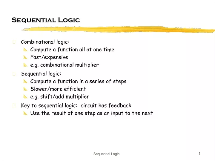
Sequential Logic. Combinational logic: Compute a function all at one time Fast/expensive e.g. combinational multiplier Sequential logic: Compute a function in a series of steps Slower/more efficient e.g. shift/add multiplier Key to sequential logic: circuit has feedback

E N D
Sequential Logic • Combinational logic: • Compute a function all at one time • Fast/expensive • e.g. combinational multiplier • Sequential logic: • Compute a function in a series of steps • Slower/more efficient • e.g. shift/add multiplier • Key to sequential logic: circuit has feedback • Use the result of one step as an input to the next Sequential Logic
Circuits with feedback • How to control feedback? • what stops values from cycling around endlessly? • this is an asynchronous sequential circuit X1X2•••Xn Z1Z2•••Zn Combinational circuit Sequential Logic
"1" "stored value" "0" "remember" "load" "stored value" "data" Simplest circuits with feedback: latch • Two inverters form a static memory cell • will hold value as long as it has power applied • How to get a new value into the memory cell? • selectively break feedback path • load new value into cell Sequential Logic
Let’s Use This Latch • What happens? X1X2•••Xn Z1Z2••• Combinational circuit Sequential Logic
What We Need: • When inputs change... • Wait until combinational logic has finished and result it stable... • Then sample the output value and save... • Feed the saved output back to the input of the combinational logic • Make sure the saved output can’t change • Key idea: we sample the result at the right time, i.e. when it is ready • Only then do we update the stored value • How do we know when to sample? • How do we know when the inputs changed? • How do we know how long to wait? Sequential Logic
D Q What We Need: • A circuit that can sample a value • A signal that says when to sample • Edge-triggered D flip-flop (register) • Samples on positive edge of clock • Holds value until next positive edge • Most common storage element • Clock • Periodic signal, each rising edge signals D flip-flops to sample • All registers sample at the same time Sequential Logic
D Q Let’s Use This D flip-flop • Does this work? • What do we need to say about the inputs X1, X2, ...? • This is a synchronous sequential circuit X1X2•••Xn Z1Z2••• Combinational circuit Sequential Logic
D D Q Q Registers • Sample data using clock • Hold data between clock cycles • Computation (and delay) occurs between registers data in data out clock stable may change data in clock stable stable stable data out (Q) Sequential Logic
Example - Circuit with Feedback • Output is a function of arbitrarily many past inputs Sequential Logic
B A outt outt+1– 0 0 0– 0 1 10 1 – 01 1 – 1 Examples (cont’d) • Output is a function of inputs and the previous state of the circuit Sequential Logic
Example - Circuit without Feedback • Output is a function of the input sampled at three different points in time Sequential Logic
D D Q Q Tsu Th input clock Timing Methodologies (cont’d) • Definition of terms • setup time: minimum time before the clocking event by which the input must be stable (Tsu) • hold time: minimum time after the clocking event until which the input must remain stable (Th) data clock there is a timing "window" around the clocking event during which the input must remain stable and unchanged in order to be recognized stable changing data clock Sequential Logic
Tsu5ns Th2ns D Tsu5ns Th2ns CLK Tw 7ns Tplh5ns3ns Tphl7ns5ns Q Typical timing specifications • Positive edge-triggered D flip-flop • setup and hold times • minimum clock width • propagation delays (low to high, high to low, max and typical) all measurements are made from the clocking event that is, the rising edge of the clock Sequential Logic
D D Q Q Cascaded Flip-Flops • Shift register: new value to first stage while second state obtains current value of first stage • Outputs change only on clock tick Q0 Q1 IN OUT CLK Sequential Logic
Cascaded Flip-Flops (cont’d) • Contamination delay > hold time • next stage latches current value before it is replaced by new value • Clock period > propagation delays + setup time • new value must arrive early enough to be seen at next clock event • Timing constraints guarantee proper operation of cascaded components • Assumes infinitely fast distribution of clock signal In Q0 Q1 CLK Tsu 5ns Tsu 5ns Tcd 3ns Tcd 3ns Th 2ns Th 2ns Sequential Logic
Q0 Q1 IN OUT CLK0 CLK1 delay D D Q Q IN Q0 Q1 CLK0 CLK1 IN Q0 Q1 CLK0 CLK1 Effect of Clock Skew Sequential Logic
Clock Skew • Correct behavior assumes that all storage elements sample at exactly the same time • Not possible in real systems: • clock driven from some central location • different wire delay to different points in the circuit • Problems arise if skew is of the same order as FF contamination delay • Gets worse as systems get faster (wires don't improve as fast) • 1) distribute clock signals in general direction of data flow • 2) wire carrying the clock between two communicating components should be as short as possible • 3) try to make all wires from the clock generator be the same length – clock tree Sequential Logic
Other Types of Latches and Flip-Flops • Best choice is D-FF simplest design technique, minimizes number of wires preferred in PLDs and FPGAs good choice for data storage register edge-triggered has most straightforward timing constraints • Historically J-K FF was popular versatile building block, usually requires least amount of logic to implement function two inputs require more wiring and logic (e.g., two two-level logic blocks in PLDs) good in days of TTL/SSI, not a good choice for PLDs and FPGAs can always be implemented using D-FF • Level-sensitive latches in special circumstances popular in VLSI because they can be made very small (4 transistors) fundamental building block of all other flip-flop types two latches make a D-FF • Preset and clear inputs are highly desirable Sequential Logic
D Q D Q Comparison of latches and flip-flops D CLK Qedge Qlatch CLK positiveedge-triggeredflip-flop CLK transparent, flow-through(level-sensitive)latch behavior is the same unless input changes while the clock is high Sequential Logic
What About External Inputs? • Internal signals are OK • Can only change when clock changes • External signals can change at any time • Asynchronous inputs • Truly asynchronous • Produced by a different clock • This means register may sample a signal that is changing • Violates setup/hold time • What happens? Sequential Logic
Synchronization failure • Occurs when FF input changes close to clock edge • the FF may enter a metastable state – neither a logic 0 nor 1 – • it may stay in this state an indefinite amount of time • this is not likely in practice but has some probability logic 1 logic 0 logic 0 logic 1 oscilloscope traces demonstrating synchronizer failure and eventual decay to steady state small, but non-zero probability that the FF output will get stuck in an in-between state Sequential Logic
Calculating probability of failure • For a single synchronizer Mean-Time Between Failure (MTBF) = exp ( tr / ) / ( T0 f a )where a failure occurs if metastability persists beyond time tr after a clock edge • tr is the resolution time - extra time in clock period for settling • Tclk - (tpd + TCL + tsetup) • f is the frequency of the FF clock • a is the number of asynchronous input changes per second applied to the FF • T0 and are constaints that depend on the FF's electrical characteristics (e.g., gain or steepness of curve) • typical values are T0 = .4s and = 1.5ns (sensitive to temperature, voltage, cosmic rays, etc.). • Must add probabilities from all synchronizers in system 1/MTBFsystem = 1/MTBFsynch these are justaverages Sequential Logic
Metastability • Example • input changes at 1 MHz • system clock of 10MHz, flipflop (tpd + tsetup) = 5ns MTBF = exp( 95ns / 1.5ns ) / ( .4s 107106 ) = 25 million years • if we go to 20MHz then: MTBF = exp( 45ns / 1.5ns ) / ( .4s 2107106 ) = 1.33 seconds! • Must do the calculations and allow enough time for synchronization Sequential Logic
Guarding against synchronization failure • Give the register time to decide • Probability of failure cannot be reduced to 0, but it can be reduced • Slow down the system clock? • Use very fast technology for synchronizer -> quicker decision? • Cascade two synchronizers? Q asynchronous input synchronized input D Q D Clk Sequential Logic
D Q D Q Another Problem with Asynchronous inputs • What goes wrong here? (Hint: it’s not a metastability thing) • What is the fix? Q0 Async Input Clock Q1 Clock Sequential Logic
Flip-flop Extras • Reset (set state to 0) – R • synchronous: Dnew = R' • Dold (when next clock edge arrives) • asynchronous: doesn't wait for clock, quick but dangerous • Preset or set (set state to 1) – S (or sometimes P) • synchronous: Dnew = Dold + S (when next clock edge arrives) • asynchronous: doesn't wait for clock, quick but dangerous • Both reset and preset • Dnew = R' • Dold + S (set-dominant) • Dnew = R' • Dold + R'S (reset-dominant) • Selective input capability (input enable or load) – LD or EN • multiplexor at input: Dnew = LD' • Q + LD • Dold • load may or may not override reset/set • Complementary outputs – Q and Q’ • Output enable - tristate output Sequential Logic
OUT1 OUT2 OUT3 OUT4 Reset R S R S R S R S D Q D Q D Q D Q CLK IN1 IN2 IN3 IN4 Registers • Collection of flip-flops with same control • stored values somehow related (for example, form binary value) • Examples • shift registers • counters Sequential Logic
OUT1 OUT2 OUT3 OUT4 D Q D Q D Q D Q IN CLK Shift register • Holds samples of input • store last 4 input values in sequence • 4-bit shift register: Sequential Logic
output left_in right_out left_out right_in clear s0 clock s1 input 4-bit Universal shift register • Holds 4 values • serial or parallel inputs • serial or parallel outputs • permits shift left or right • shift in new values from left or right clear sets the register contentsand output to 0s1 and s0 determine the shift function s0 s1 function 0 0 hold state 0 1 shift right 1 0 shift left 1 1 load new input Sequential Logic
0 1 2 3 Design of Universal Shift Register clear s0 s1 new value 1 – – 0 0 0 0 output 0 0 1 output value of FF to left (shift right) 0 1 0 output value of FF to right (shift left) 0 1 1 input • Consider one of the four flip-flops • new value at next clock cycle: Nth cell to N-1th cell to N+1th cell Q D CLK CLEAR s0 and s1control mux Q[N-1](left) Q[N+1](right) Input[N] Sequential Logic
OUT0 OUT1 OUT2 OUT3 D Q D Q D Q D Q CLK "1" Binary counter • Next state function for bit i • XOR acts like a “programmable” inverter • if bits 0:i-1 are 1, then toggle bit i • requires an i-input AND for bit i • Synchronous: outputs all change when clock ticks Sequential Logic
ENDCBA LOAD CLK CLR RCO QDQCQBQA Example: 4-bit binary synchronous counter • Typical library component • positive edge-triggered FFs w/ synchronous load and clear inputs • parallel load data from D, C, B, A • enable input: assert to enable counting • RCO: “ripple-carry out” used for cascading counters • high when counter is in its highest state 1111 • implemented using an AND gate (2) RCO goes high CLK (1) Low order 4-bits = 1111 Sequential Logic
OUT1 OUT2 OUT3 OUT4 D Q D Q D Q D Q IN CLK OUT1 OUT2 OUT3 OUT4 D Q D Q D Q D Q IN CLK Other Counters: cheaper/faster • Sequences through a fixed set of patterns • in this case, 1000, 0100, 0010, 0001 • if one of the patterns is its initial state (by loading or set/reset) • Mobius (or Johnson) counter • in this case, 1000, 1100, 1110, 1111, 0111, 0011, 0001, 0000 Sequential Logic