Download

1 / 64
670 likes | 1.01k Views
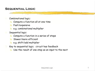
Sequential Logic. Lecture #7. 강의순서. Latch FlipFlop Shift Register Counter. SR Latch. Most simple “ storage element ” . Q next = (R + Q ’ current ) ’ Q ’ next = (S + Q current ) ’. NOR. In1 In2 Out 0 0 1 0 1 0 1 0 0 1 1 0. Function Table. Storing. SR latches are sequential.

E N D
Sequential Logic Lecture #7
강의순서 • Latch • FlipFlop • Shift Register • Counter 모바일컴퓨팅특강
SR Latch • Most simple “storage element”. Qnext = (R + Q’current)’ Q’next = (S + Qcurrent)’ NOR In1 In2 Out 0 0 1 0 1 0 1 0 0 1 1 0 Function Table Storing 모바일컴퓨팅특강
SR latches are sequential • For inputs SR = 00, the next value of Q depends on the current value of Q. • So the same inputs can yield different outputs. • This is different from the combinational logics. 모바일컴퓨팅특강
S R Q Q’ Set Reset Timing Diagram for S-R Latch 모바일컴퓨팅특강
SR latch simulation 모바일컴퓨팅특강
0 0 0 0 0 1 1 0 What about SR = 11? Qnext = (R + Q’current)’ Q’next = (S + Qcurrent)’ • Both Qnext and Q’next will become 0. • If we then make S = 0 and R = 0 together, Qnext = (0 + 0)’ = 1 Q’next = (0 + 0)’ = 1 • But these new values go back into the NOR gates, and in the next step we get: Qnext = (0 + 1)’ = 0 Q’next = (0 + 1)’ = 0 • The logic enters an infinite loop, where Q and Q’ cycle between 0 and 1 forever. (Unstable) • This is actually the worst case, so we have to avoid setting SR=11. 모바일컴퓨팅특강
An SR latch with a control input(Gated SR latch) • The dotted blue box is the S’R’ latch from the previous slide. • The additional NAND gates are simply used to generate the correct inputs for the S’R’ latch. • The control input acts just like an enable. 모바일컴퓨팅특강
D latch (Gated D latch) • D latch is based on an S’R’ latch. The additional gates generate the S’ and R’ signals, based on inputs D (“data”) and C (“control”). • When C = 0, S’ and R’ are both 1, so the state Q does not change. • When C = 1, the latch output Q will equal the input D. • Single input for both set and reset • Also, this latch has no “bad” input combinations to avoid. Any of the four possible assignments to C and D are valid. 모바일컴퓨팅특강
Timing diagram for D Latch Q follows D while EN is HIGH. 모바일컴퓨팅특강
D latch with BDF 모바일컴퓨팅특강
D latch simulation with Primitive • Insert the symbol latch 모바일컴퓨팅특강
Simulation result with Primitive 모바일컴퓨팅특강
D latch simulation with VHDL file 모바일컴퓨팅특강
Q D1 Q1 D2 Q2 D D Latch D Latch C Q’ C Q2’ C The D Flip-Flop : Edge triggering • The D flip-flop is said to be “edge triggered” since the output Q only changes on the rising edge (positive edge) of the clock signal 모바일컴퓨팅특강
Timing Diagram for a D-FF C D shift Q1 shift Q Positive Edge Triggering 모바일컴퓨팅특강
D-FF with Direct Inputs • Most flip-flops provide direct, or asynchronous, inputs that immediately sets or clears the state. • The below is a D flip-flop with active-low direct inputs. Direct inputs to set or reset the flip-flop S’R’ = 11 for “normal” operation of the D flip-flop 모바일컴퓨팅특강
D-FF with BDF • Insert the symbol dff Edge-trigger symbol 모바일컴퓨팅특강
D-FF with VHDL file 모바일컴퓨팅특강
D-FF with active-high Clock & asynchronous Clear library ieee; use ieee.std_logic_1164.all; entity dff_1 is port( d, clk, nclr : in std_logic; q : out std_logic ); end dff_1 ; architecture a of dff_1 is begin process(nclr,clk) begin if( nclr='0') then q <='0'; elsif(clk'event and clk='1') then q <= d; end if; end process; end a; 모바일컴퓨팅특강
D-FF with active- low Clock & asynchronous Clear library ieee; use ieee.std_logic_1164.all; entity dff_fall_1 is port( d, clk, nclr : in std_logic; q : out std_logic ); end dff_fall_1 ; architecture a of dff_fall_1 is begin process(nclr,clk) begin if( nclr='0') then q <='0'; elsif(clk'event and clk=‘0') then q <= d; end if; end process; end a; 모바일컴퓨팅특강
D-FF with active-high Clock & asynchronous Preset library ieee; use ieee.std_logic_1164.all; entity dff_ preset_1 is port( d, clk, npre : in std_logic; q : out std_logic ); end dff_ preset_1 ; architecture a of dff_ preset_1 is begin process(npre,clk) begin if( npre='0') then q <=‘1'; elsif(clk'event and clk=‘1') then q <= d; end if; end process; end a; 모바일컴퓨팅특강
D-FF with active-high Clock & asynchronous Clear & Preset library ieee; use ieee.std_logic_1164.all; entity dff_ presetclr_1 is port( d, clk, npre,nclr : in std_logic; q : out std_logic ); end dff_ presetclr_1 ; architecture a of dff_ presetclr_1 is begin process(npre, nclr, clk) begin if( npre='0') then q <=‘1'; elsif( nclr='0') then q <=‘0'; elsif(clk'event and clk=‘1') then q <= d; end if; end process; end a; 모바일컴퓨팅특강
JK-FF & T-FF • JK=11 are used to complement the flip-flop’s current state. • A T flip-flop can only maintain or complement its current state. 모바일컴퓨팅특강
7474 Dual D-FF • Insert the symbol others > quartus II > 7474 모바일컴퓨팅특강
7474 Dual D-FF “Datasheet” from Philips • Plastic dual in-line package 모바일컴퓨팅특강
Set-up and hold times • For proper operation the D input to a D flip-flop should be stable for certain prescribed times before and after the rising clock edge. These are referred to as the set-up and hold times respectively 모바일컴퓨팅특강
Set-up time (ts) • The logic level must be present on the D input for a time equal to or greater than ts before the triggering edge of the clock pulse for reliable data entry. 모바일컴퓨팅특강
Hold time (th) • The logic level must remain on the D input for a time equal to or greater than th after the triggering edge of the clock pulse for reliable data entry. 모바일컴퓨팅특강
C Hold time D Q Set-up time Propagation delay D-FF timing constraints 모바일컴퓨팅특강
Propagation Delay (1) • As with any other circuit there will be a propagation delay between the rising edge of the clock and the time that the outputs of the flip-flop are stable. 모바일컴퓨팅특강
Propagation delay (2) 모바일컴퓨팅특강
Clock Period Clock Frequency = 1 / Clock Period Clock Signal • Periodic signal, generated by an oscillator which acts as the heartbeat of a synchronous digital system 모바일컴퓨팅특강
Synchronous Systems • In a synchronous system, all of the state elements are connected to the same clock signal. • This means that they all change state at the same time. 모바일컴퓨팅특강
Gates Gates Gates tp gates tp routing Total propagation delay through combinational logic Timing Characteristics (1) • Propagation delays • through logic components (gates) • through interconnects (routing delays) 모바일컴퓨팅특강
Timing Characteristics (2) • Total propagation delay of logic (Sum of tp gate) depends on the number of logic levels and delays of logic components • Number of logic levels is the number of logic components (gates) the signal propagates through • Routing delays (tp routing) depend on: • Length of interconnects • Fanout 모바일컴퓨팅특강
Gates Gates Gates Gates Timing Characteristics (3) • Fanout – Number of inputs connected to one output • Each inputs has its capacitance • Fast switching of outputs with high fanout requires higher currents This makes a larger delay. 모바일컴퓨팅특강
Timing Characteristics (4) • In Current Technologies Routing Delays Make 50-70% of the Total Propagation Delays 모바일컴퓨팅특강
. . . . . . . . . . . . Clk Critical Path & Cycle Time • Critical path: the slowest path between any two storage devices • Cycle time is a function of the critical path • must be greater than: Clock-to-Q + Longest Path through Combinational Logic + Setup
Critical Path • Min. Clock Period = Length of The Critical Path • Max. Clock Frequency = 1 / Min. Clock Period 모바일컴퓨팅특강
clk Clock Jitter • Rising Edge of The Clock Does Not Occur Precisely Periodically • May cause faults in the circuit 모바일컴퓨팅특강
out in clk delay out in D D Q Q D D Q Q clk delay Clock Skew • Rising Edge of the Clock Does Not Arrive at Clock Inputs of All Flip-flops at The Same Time 모바일컴퓨팅특강
Dealing With Clock Problems • Use Only Dedicated Clock Nets for Clock Signals • Do Not Put Any Logic in Clock Nets 모바일컴퓨팅특강
Register • Flip-Flip을 응용한 데이터 저장장치 • 가장 기본적인 순차논리회로 • Multi-bit Register • Shift Register • Counter Register 모바일컴퓨팅특강
8 8 Resetn D Q Clock reg8 8-bit register with asynchronous reset LIBRARY ieee ; USE ieee.std_logic_1164.all ; ENTITY reg8 IS PORT ( D : IN STD_LOGIC_VECTOR(7 DOWNTO 0) ; Resetn, Clock : IN STD_LOGIC ; Q : OUT STD_LOGIC_VECTOR(7 DOWNTO 0) ) ; END reg8 ; ARCHITECTURE Behavior OF reg8 IS BEGIN PROCESS ( Resetn, Clock ) BEGIN IF Resetn = '0' THEN Q <= "00000000" ; ELSIF Clock'EVENT AND Clock = '1' THEN Q <= D ; END IF ; END PROCESS ; END Behavior ;` 모바일컴퓨팅특강
N N Resetn D Q Clock regn N-bit register with asynchronous reset LIBRARY ieee ; USE ieee.std_logic_1164.all ; ENTITY regn IS GENERIC ( N : INTEGER := 16 ) ; PORT ( D : IN STD_LOGIC_VECTOR(N-1 DOWNTO 0) ; Resetn, Clock : IN STD_LOGIC ; Q : OUT STD_LOGIC_VECTOR(N-1 DOWNTO 0) ) ; END regn ; ARCHITECTURE Behavior OF regn IS BEGIN PROCESS ( Resetn, Clock ) BEGIN IF Resetn = '0' THEN Q <= (OTHERS => '0') ; ELSIF Clock'EVENT AND Clock = '1' THEN Q <= D ; END IF ; END PROCESS ; END Behavior ; 모바일컴퓨팅특강
N N N-bit register with Enable LIBRARY ieee ; USE ieee.std_logic_1164.all ; ENTITY regn IS GENERIC ( N : INTEGER := 8 ) ; PORT ( D : IN STD_LOGIC_VECTOR(N-1 DOWNTO 0) ; Enable, Clock : IN STD_LOGIC ; Q : OUT STD_LOGIC_VECTOR(N-1 DOWNTO 0) ) ; END regn ; ARCHITECTURE Behavior OF regn IS BEGIN PROCESS (Clock) BEGIN IF (Clock'EVENT AND Clock = '1' ) THEN IF Enable = '1' THEN Q <= D ; END IF ; END IF; END PROCESS ; END Behavior ; Enable Q D Clock regn 모바일컴퓨팅특강