Download
1 / 41
410 likes | 516 Views
Sequential Logic. Handouts: Lecture Slides. 6.004: Progress so far…. PHYSICS: Continuous variables, Memory, Noise, f(RC) = 1 - e-t/R. COMBINATIONAL: Discrete, memoryless, noise-free, lookup table functions. What other building blocks do we need in order to compute?.

E N D
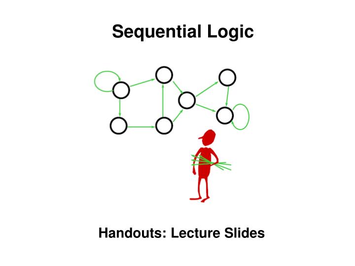
Sequential Logic Handouts: Lecture Slides
6.004: Progress so far… PHYSICS: Continuous variables, Memory, Noise, f(RC) = 1 - e-t/R COMBINATIONAL: Discrete, memoryless, noise-free, lookup table functions What other building blocks do we need in order to compute?
Something We Can’t Build (Yet) What if you were given the following design specification: When the button is pushed: 1) Turn on the light if it is off 2) Turn off the light if it is on The light should change state within a second of the button press button light What makes this circuit so different from those we’ve discussed before? 1. “State” – i.e. the circuit has memory 2. The output was changed by a input “event” (pushing a button) rather than an input “value”
Digital StateOne model of what we’d like to build New State Memory Device LOAD Current State Combinational Logic Input Output • Plan: Build a Sequential Circuit with stored digital STATE – • • Memory stores CURRENT state, produced at output • • Combinational Logic computes • • NEXT state (from input, current state) • • OUTPUT bit (from input, current state) • • State changes on LOAD control input
Needed: Storage Combinational logic is stateless: valid outputs always reflect current inputs. To build devices with state, we need components which store information (e.g., state) for subsequent access. ROMs (and other combinational logic) store information “wired in” to their truth table Read/Write memory elements are required to build devices capable of changing their contents. How can we store – and subsequently access -- a bit? • Mechanics: holes in cards/tapes • Optics: Film, CDs, DVDs, … • Magnetic materials • Delay lines; moonbounce • Stored charge
To write: Drive bit line, turn on access fet, force storage cap to new voltage To read: precharge bit line, turn on access fet, detect (small) change in bit line voltage Pros: compact – low cost/bit (on BIG memories) Cons: complex interface stable? (noise, …) it leaks! ⇒ refresh Suppose we refresh CONTINUOUSLY? Storage: Using Capacitors We’ve chosen to encode information using voltages and we know from 6.002 that we can “store” a voltage as charge on a capacitor: word line Bit line N-channel fet serves as access switch VREF
Storage: Using Feedback IDEA: use positive feedback to maintain storage indefinitely. Our logic gates are built to restore marginal signal levels, so noise shouldn’t be a problem! Result: a bistable storage element VTC for inverter pair Not affected by noise Feedback constraint: • Three solutions: • two end-points are stable • middle point is unstable We’ll get back to this!
Settable Storage Element It’s easy to build a settable storage element (called a latch) using a lenient MUX: “state” signal appears as both input and output Here’s a feedback path, so it’s no longer a combinational circuit. Q stable Q follows D
New Device: D Latch G=1: Q follows D G=0: Q holds BUT… A change in D or G contaminates Q, hence Q’ … how can this possibly work? G=1: Q Follows D, independently of Q’ G=0: Q Holds stable Q’, independently of D
A Plea for Lenience… • Assume LENIENT Mux, propagation • delay of TPD • Then output valid when • • Q’=D stable for TPD , • independently of G; • or • • G=1, D stable for TPD, • independently of Q’; • or • • G=0, Q’ stable for TPD , • independently of D Does lenience guarantee a working latch? What if D and G change at about the same time…
… with a little discipline D stable • To reliably latch V2: • • Apply V2 to D, holding G=1 • • After another TPD, Q’ & D both valid for TPD; will hold Q=V2 independently of G • • Set G=0, while Q’ & D hold Q=D • • After TPD, V2 appears at Q=Q’ • • After another TPD,G=0 and Q’ are sufficient to hold Q=V2 • independently of D Dynamic Discipline for our latch: TSETUP = 2TPD: interval prior to G transition for which D must be stable & valid THOLD = TPD: interval following G transition for which D must be stable & valid
Lets try it out! New State Current State Combinational Logic Input Output • Plan: Build a Sequential Circuit with one bit of STATE – • • Single latch holds CURRENT state • • Combinational Logic computes • • NEXT state (from input, current state) • • OUTPUT bit (from input, current state) • • State changes when G = 1 (briefly!) What happens when G=1?
Combinational Cycles New State Current State Combinational Logic Input Output • When G=1, latch is Transparent… • … provides a combinational path from D to Q. • Can’t work without tricky timing constrants on G=1 pulse: • • Must fit within contamination delay of logic • • Must accommodate latch setup, hold times • Want to signal an INSTANT, not an INTERVAL…
Flakey Control Systems Here’s a strategy for saving 2 bucks on the Sumner Tunnel!
Flakey Control Systems Here’s a strategy for saving 2 bucks on the Sumner Tunnel
Flakey Control Systems Here’s a strategy for saving 2 bucks on the Sumner Tunnel WARNING: Professional Driver Used ! Don’t try this At home !
Escapement Strategy The Solution: Add two gates and only open one at a time.
Escapement Strategy The Solution: Add two gates and only open one at a time.
Escapement Strategy The Solution: Add two gates and only open one at a time.
Escapement Strategy The Solution: Add two gates and only open one at a time. (Psst… Don’t tell Massport)
Escapement Strategy The Solution: Add two gates and only open one at a time. (Psst… Don’t tell Massport)
Escapement Strategy The Solution: Add two gates and only open one at a time. (Psst… Don’t tell Massport)
Escapement Strategy The Solution: Add two gates and only open one at a time. (Psst… Don’t tell Massport)
Escapement Strategy The Solution: Add two gates and only open one at a time.
Escapement Strategy The Solution: Add two gates and only open one at a time.
Escapement Strategy The Solution: Add two gates and only open one at a time. (Psst… Don’t tell Massport)
Escapement Strategy The Solution: Add two gates and only open one at a time. (Psst… Don’t tell Massport)
Escapement Strategy The Solution: Add two gates and only open one at a time. (Psst… Don’t tell Massport)
Escapement Strategy The Solution: Add two gates and only open one at a time. (Psst… Don’t tell Massport)
Escapement Strategy The Solution: Add two gates and only open one at a time.
Escapement Strategy The Solution: Add two gates and only open one at a time.
Escapement Strategy The Solution: Add two gates and only open one at a time. (Psst… Don’t tell Massport) KEY: At no time is there an open path through both gates…
Edge-triggered Flip Flop The gate of this latch is open when the clock is low master slave The gate of this latch is open when the clock is high • Observations: • only one latch “transparent” at any time: • master closed when slave is open • slave closed when master is open • → no combinational path through flip flop • Q only changes shortly after 0 →1 • transition of CLK, so flip flop appears • to be “triggered” by rising edge of CLK Transitions mark instants, not intervals (the feedback path in one of the master or slave latches is always active)
Flip Flop Waveforms master slave CLK master closed slave open slave closed master open
Um, about that hold time… The master’s contamination delay must meet the hold time of the slave master slave • Consider HOLD TIME requirement for slave: • • Negative (1 →0) clock transition → slave freezes data: • • SHOULD be no output glitch, since master held constant data; BUT • • master output contaminated by change in G input! • • HOLD TIME of slave not met, UNLESS we assume sufficient • contamination delay in the path to its D input! • Accumulated tCD thru inverter, G → Q path of master must cover • slave tHOLD for this design to work!
Flip Flop Timing - I tPD: maximum propagation delay, CLK →Q tCD: minimum contamination delay, CLK →Q • tSETUP: setup time • guarantee that D has propagated through feedback path before master closes • tHOLD: hold time • guarantee master is closed and data is stable before allowing D to change
Single-clock Synchronous Circuits We’ll use Flip Flops and Registers – groups of FFs sharing a clock input – in a highly constrained way to build digitial systems: Does that symbol register? • Single-clock Synchronous Discipline • • No combinational cycles • •Only care about value of combinational • circuits just before rising edge of • clock • • Single clock signal shared among • all clocked devices • •Period greater than every • combinational delay • • Change saved state after noiseinducing • logic transitions have • stopped!
Flip Flop Timing - II • Questions for register-based designs: • how much time for useful work • (i.e. for combinational logic • delay)? • does it help to guarantee a • minimum tCD? How ‘bout • designing registers so that • tCD,reg > tHOLD,reg? • what happens if CLK signal • doesn’t arrive at the two • registers at exactly the • same time (a phenomenon • known as “clock skew”)?
Model: Discrete Time New State Memory Device Current State Combinational Logic Clock Input Output • Active Clock Edges punctuate time --- • • Discrete Clock periods • • Discrete State Variables • • Discrete specifications (simple rules – eg tables – relating • outputs to inputs, state variables) • • ABSTRACTION: Finite State Machines (next lecture!)
Model: Discrete Time New State Current State Combinational Logic Clock Input Output Questions: • Constraints on TCD for the logic? • Minimum clock period? • Setup, Hold times for Inputs? This is a simple Finite State Machine … more on Thursday!
Summary“Sequential” Circuits (with memory): • Basic memory elements: • • Feedback, detailed analysis => • basic level-sensitive devices • (eg, latch) • • 2 Latches => Flop • • Dynamic Discipline: • constraints on input timing • Synchronous 1-clock logic: • • Simple rules for sequential • circuits • • Yields clocked circuit with TS, TH • constraints on input timing • Finite State Machines • Thursday’s Topic!