Download
1 / 6
60 likes | 77 Views
The Flame Photometric Detector is similar to the FID in that the sample exits the analytical column into a hydrogen diffusion flame. Where the FID measures ions produced by organic compounds during combustion, the FPD analyzes the spectrum of light emitted by the compounds as they luminesce in the flame. Visit - http://quadrexcorp.com/<br>

E N D
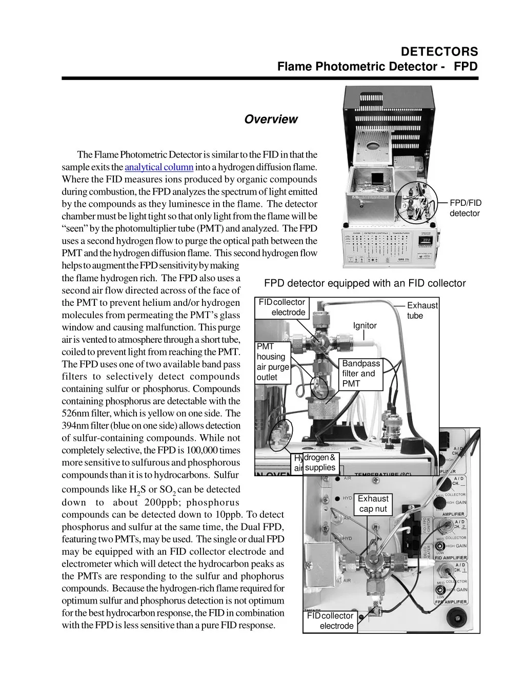
DETECTORS Flame Photometric Detector - FPD Overview The Flame Photometric Detector is similar to the FID in that the sample exits the analytical column into a hydrogen diffusion flame. Where the FID measures ions produced by organic compounds during combustion, the FPD analyzes the spectrum of light emitted by the compounds as they luminesce in the flame. The detector chamber must be light tight so that only light from the flame will be “seen” by the photomultiplier tube (PMT) and analyzed. The FPD uses a second hydrogen flow to purge the optical path between the PMT and the hydrogen diffusion flame. This second hydrogen flow helps to augment the FPD sensitivity by making the flame hydrogen rich. The FPD also uses a second air flow directed across of the face of the PMT to prevent helium and/or hydrogen molecules from permeating the PMT’s glass window and causing malfunction. This purge air is vented to atmosphere through a short tube, coiled to prevent light from reaching the PMT. The FPD uses one of two available band pass filters to selectively detect compounds containing sulfur or phosphorus. Compounds containing phosphorus are detectable with the 526nm filter, which is yellow on one side. The 394nm filter (blue on one side) allows detection of sulfur-containing compounds. While not completely selective, the FPD is 100,000 times more sensitive to sulfurous and phosphorous compounds than it is to hydrocarbons. Sulfur compounds like H2S or SO2 can be detected down to about 200ppb; phosphorus compounds can be detected down to 10ppb. To detect phosphorus and sulfur at the same time, the Dual FPD, featuring two PMTs, may be used. The single or dual FPD may be equipped with an FID collector electrode and electrometer which will detect the hydrocarbon peaks as the PMTs are responding to the sulfur and phophorus compounds. Because the hydrogen-rich flame required for optimum sulfur and phosphorus detection is not optimum for the best hydrocarbon response, the FID in combination with the FPD is less sensitive than a pure FID response. FPD/FID detector FPD detector equipped with an FID collector FID collector electrode Exhaust tube Ignitor PMT housing air purge outlet Bandpass filter and PMT drogen & supplies air Hy Exhaust cap nut FID collector electrode
DETECTORS Flame Photometric Detector - FPD Theory of Operation The FPD uses one of two available band pass filters over a photomultiplier tube (PMT) to selectively detect compounds containing sulfur or phosphorus as they combust in the hydrogen flame. When compounds are burned in the FPD flame, they emit photons of distinct wavelengths. Only those photons that are within the frequency range of the filter specifications can pass through the filter to the PMT. The PMT converts the photons it “sees” through the bandpass filter to an analog signal, which is acquired by the Peak Simple data system. Simplified FPD Schematic Exhaust tube Ignitor blade Jet Ignitor Column effluent Photons Ferrule Air inlet Primary H2 inlet to jet Bandpass filter over PMT window (394nm for sulfur, 526nm for phosphorus) H2 Secondary H2 inlet into PMT housing Purge air inlet Purge air outlet Stainless steel retaining nut Rubber o-ring Photomultiplier tube (PMT) Photomultiplier signal cable to amplifier Split TeflonTM ferrule 10-pin socket
DETECTORS Flame Photometric Detector - FPD Expected Performance FPD Noise Run (FID/FPD Combo) Column: 15m MXT-1 Carrier: Helium @ 10mL/min FPD gain: HIGH FPD temp: 150oC FPD PMT volts: -400 FPD H2: 60mL/min (30mL/min for each of the two hydrogen flows) FPD air: 100mL/min FPD noise averages less than 100µV from peak to peak FPD Sulfur (FID/FPD Combo) Sample: 1cc 10ppm H2S in 3 replicate injections to demonstrate the consistency of the FPD response Column: 15m MXT-1 Carrier: Helium @ 10mL/min FPD gain: HIGH; FPD temp: 150oC FPD PMT volts: -400 FPD H2: 60mL/min (30mL/min for each of the two hydrogen flows) FPD air: 100mL/min Temperature Program: Initial Hold 60oC 60.00 Ramp 0.00 Final 60oC Results: Component Hydrogen Sulfide Hydrogen Sulfide Hydrogen Sulfide Retention 6.550 7.533 8.516 Total Area 5216.6680 4828.8710 4810.5420 14856.0810 FPD Phosphorus Sample: 1µL 10ppm malathion Column: 15m MXT-1 Carrier: helium @ 10mL/min FPD PMT volts: -400 FPD H2: 30mL/min FPD air: 100mL/min FPD temp: 250oC Temperature Program: Initial Hold 225oC 10.00 Ramp Final 0.00 225oC Results: Component Retention Area Malathion 4.916 2819.0520
DETECTORS Flame Photometric Detector - FPD General Operating Procedure 1.Set the hydrogen flow to 60mL/min. This correlates to a flow of 30mL/min each for the primary and secondary hydrogen. Set the air supply to 100mL/min. The air supply tubing is T’d inside the GC so that 10- 30mL/min of air flows across the face of the PMT. Set the carrier gas flow between 5 and 20mL/min. 2.Use the switch on the GC’s front control panel to light the FPD flame. Sometimes the flame is difficult to light because of the hydrogen-rich atmosphere inside the FPD detector body. If you are having difficulty lighting it, make sure the PMT voltage is OFF, then remove the cap on the FPD exhaust port and try the ignitor switch again. When the flame lights, there will be a loud noise like the backfiring of a car; this is normal and does not indicate a problem. KEEP YOUR FACE AWAY FROM THE DETECTOR WHILE LIGHTING THE FLAME; the loud noise is accompanied by a flash of flame. Replace the exhaust cap nut after lighting the flame. 3.Switch on the PMT voltage and set it to 400 by using the provided flat blade screwdriver to adjust the trimpot setpoint on the top edge of the GC’s front control panel (vertically labeled “PMTVOLTS” under “DETECTORPARAMETERS”). 4.Set the FPD temperature to 150oC by adjusting the appropriate trimpot setpoint. Set the FPD gain to HIGH. Allow the FPD signal to stabilize, then inject the sample. Optimizing Sensitivity To optimize your FPD detector’s sensitivity, inject the same sample at varying air and hydrogen pressures and observe the fluctuations in sensitivity. 1.Inject sample and observe the FPD response. 2.Turn the air up a tiny bit, less than 1psi, inject sample and observe the FPD response again. If you see an improvement in sensitivity, adjust the air up a little more, inject again and observe the response. Keep adjusting the air pressure up until sensitivity drops again to find the window of optimum sensitivity. 3.If there is no improvement in sensitivity after turning the air up, turn the air down less than 1psi, inject sample and observe the FPD response. If you see an improvement in sensitivity, adjust the air down a little more, inject again and observe the response. Keep adjusting the air pressure down until sensitivity drops again to find the window of optimum sensitivity. 4.Now, turn the hydrogen pressure up 1-2psi and re-optimize the air. Repeat this until you’ve found the optimum air and hydrogen pressure settings. Note: When a large hydrocarbon peak elutes simultaneously with a target sulfur compound, the hydrocarbon peak will quench the sulfur response. For this reason, SRI recommends the addition of an FID collector electrode to the FPD detector body. The FID collector electrode will allow the operator to “see” the hydrocarbon peaks and their retention times, so that chromatographic separation can be optimized for the elution of sulfur compounds.
DETECTORS Flame Photometric Detector - FPD Switching Between Sulfur and Phophorus Modes The bandpass filter specified when the instrument was ordered comes installed in the FPD detector assembly. There are two options for switching between sulfur and phophorus modes. You can purchase either an additional filter or an additional PMT housing and switch them as necessary. Phosphorus wavelength filters are available under SRI part number 8670-0083; sulfur filters are available under SRI part number 8670-0082. A PMT housing with a bandpass filter of the other optional wavelength specifications is available under SRI part number 8670-0084 (specify sulfur or phosphorus). 1.Turn OFF the GC power. 2.Unplug the BNC cable connecting the PMT to the amplifier. Disconnect the secondary hydrogen and both air supply lines at their bulkhead fittings on the GC deck. 3.Remove the heater block cover by unscrewing the philips head screw on top of it. Slide the cover up and off the block, and carefully remove the white insulation. 4.Loosen the 1/8” Swagelok fitting that secures the FPD detector assembly on the heater block enough to gently rotate the FPD assembly about 45o toward the front of the GC (see the Front View and Side View illustrations to the right). 5.Stabilize the FPD assembly while you loosen the 1/4” Swagelok fitting that secures the PMT housing to the FPD detector body. Slide the PMT housing out of the detector body. If you’re switching PMT housing assemblies, set aside the PMT housing you just removed and skip to step number 7. If you’re switching filters, proceed to the next step. 6.Unscrew the PMT housing stainless steel retaining nut, then set it (with the PMT and its socket) aside. The bandpass filter is screwed into the top part of the PMT housing against a black o-ring, and has 2 depressions in its frame. It can be unscrewed using open needle-nosed pliers but you must be very careful not to damage or scratch the filter. FPD sensitivity will be reduced if the filter is improperly installed or dirty. 6.Inspect the black o-ring for any nicks or cuts and replace it if necessary. Place the alternate filter, with its colored side facing down toward the PMT, into the top part of the PMT housing against the black o-ring and tighten it. Remember, it must be light-tight and gas-tight. Replace and tighten the stainless steel retaining nut with the PMT in its socket. 7.Slide the top of the PMT housing containing the alternate filter into the FPD detector body, and tighten the 1/4” fitting that secures it in place. 8.Gently rotate the FPD assembly back to its original angle, and tighten (with a wrench) the 1/8” fitting that secures it to the heater block. Reconnect the gas supply lines and the BNC cable. See the note on the following page regarding proper jet positioning. Loosen this fitting +-45o GC front Front view Side view Loosen this fitting Slide the PMT housing out of the FPD body Use these depressions for filter removal Filter inside PMT housing assembly
DETECTORS Flame Photometric Detector - FPD Troubleshooting and Maintenance Changing the Photomultiplier Tube (PMT) The Photomultiplier Tube (PMT) is a consumable part, and will eventually need replacement. Additional PMTs are available under SRI part number 8670-0080. 1.Follow steps 1-4 on the “Switching Between Sulfur and Phophorus Modes”page. 2.Unscrew the stainless steel retaining nut and remove it, with the PMT and its socket, from the FPD assembly. Slide the retaining nut down the PMT amplifier lead to access the PMT. 3.Unplug the PMT from its socket. Remove the split TeflonTM ferrule and black o-ring from the PMT, inspect them for any damage, and replace them if necessary. 4.Slide the TeflonTM ferrule and black o-ring onto the new PMT. Plug the new PMT into the socket. 5.Slide the stainless steel retaining nut up and around the PMT, and screw it into place. 6.Gently rotate the FPD assembly back to its original angle, and hand tighten the 1/4” fitting that secures it. 7.Reconnect the BNC cable and the gas supply lines. Note: When your FPD detector was assembled at the factory, the ignitor and jet (and collector electrode, if present) were all properly positioned within the FPD body. It is advisable to familiarize yourself with their proper positioning in case they require adjustment. Remove the 1/4” Swagelok cap nut on the FPD exhaust port to see inside the detector body. Use a small flashlight to see the position of the jet inside the FPD detector body. The jet’s tip should be flush with the cylindrical wall of the opening that you’re looking through, and just barely visible from a slight angle. When looking straight down into the opening, you should not be able to see anything protruding into it. To adjust the jet, loosen or tighten the 1/4” Swagelok fitting to move the jet forward or backward. Keep in mind that if the jet actually protrudes into the PMT’s line of sight, it could interfere with the FPD’s performance. The ignitor should be similarly positioned across from the jet, with the tip of its blade just visible but not protruding into the FPD detector body chamber. To adjust the position of the ignitor, loosen the 1/4” fitting enough to move the ignitor forward or backward as necessary. Tighten the fitting when the ignitor is properly positioned. If there is an FID collector electrode installed on the FPD detector assembly, it must be positioned in the same manner. PMT Housing Assembly Black o-ring Bandpass filter Black o-ring Photomultiplier Tube (PMT) Split TeflonTM ferrule 10-pin socket Top view of FPD with exhaust cap nut removed Use this 1/4” fitting to adjust the position of the jet Ignitor fitting Collector fitting An angled view reveals the tip of the jet