Download

1 / 37
370 likes | 513 Views
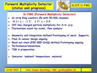
Forward detector overview. Si-FMD (Forward Multiplicity Detector) NBI+INR Si-strip Ring counters (5) with 25600 channels -5.1< < -1.7; 1.7< < 3.4 Precise off-line charged particle multiplicity for A+A, p+p Fluctuations event-by-event, flow analysis

E N D
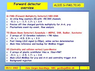
Forward detector overview Si-FMD (Forward Multiplicity Detector) NBI+INR • Si-strip Ring counters (5) with 25600 channels • -5.1< < -1.7; 1.7< < 3.4 • Precise off-line charged particle multiplicity for A+A, p+p • Fluctuations event-by-event, flow analysis T0 (Beam-Beam Detector) Jyvæskyla + MEPhI, INR, Budker, Kurchatov • 2 arrays of 12 Cerenkov radiators + PM tubes • -5< < -4.5; 2.9< < 3.3 • Fast timing LVL0 signal (=50ps), online vertex determination • Main time reference and backup for MinBias trigger V0 (Centrality and collsion vertex) Lyon+Mexico • 2 arrays of plastic scintillator tiles w. fiber+PMT • -5.1< < -2.5; 1.7< < 3.8 • Main LVL0 MinBias for p+p and A+A and centrality trigger A+A • Background rejection Jens Jørgen Gaardhøje, NBI, gardhoje@nbi.dk
Forward detectors V01.7 < |h| < 3.8and –5.1 < | h | < -2.5 Interaction trigger, centrality trigger and beam-gas rejection. Two arrays of 72 scintillator tiles readout via fibers PMD pre-shower det. T0L T0R2.9 < |h| < 3.3 T0 for the TOF (< 50 ps time res.) Two arrays of 12 quartz counters. Also backup to V0 SI-FMD Multiplicity and dn/dh 1.7 < h < 3.4 and -5.1 < h < -1.7 Silicon pad detector disks (slow readout) Jens Jørgen Gaardhøje, NBI, gardhoje@nbi.dk
Integration in ALICE Si-1 V0-R Si-2 T0-R Si-3 Jens Jørgen Gaardhøje, NBI, gardhoje@nbi.dk
Si1 inner and outer V0 Si 1 outer Si 1 outer 2 Rings 2 Rings Si 1 inner Si 1 inner T0 Jens Jørgen Gaardhøje, NBI, gardhoje@nbi.dk
Si-FMD Overall Geometry Si1 Si2 Si3 • -5.1< <-1.7 • 3.4 < < 1.7 Jens Jørgen Gaardhøje, NBI, gardhoje@nbi.dk
CERN Maquette 1:1 ITS-pixels V0-R T0-R Si1(outer) Si1 (inner) Absorber Jens Jørgen Gaardhøje, NBI, gardhoje@nbi.dk
Si rings manufactured of 6” wafers Inner: Rin=4.2 cm Rout=17.2 cm Outer: Rin=15.4 cm Rout=28.4 cm 128 256 10x2x256=5120 20x2x128=5120 Jens Jørgen Gaardhøje, NBI, gardhoje@nbi.dk
Coverage in pseudorapidity Design criteria: Largest possible coverage Largest symmetry left and right Overlap between systems Constraints: Vacuum tube outer envelope: 42 mm, Outer radius, ITS, Absorber, cables Background from secondaries(small angles) Si1: Out: 1.70< <2.29In: 2.01< <3.40 Si2: Out: -2.29<<-1.7 In: -3.68< <-2.28 Si3: In: -5.09< <-3.68 Vertex shift (10cm): |d| 0.1 Jens Jørgen Gaardhøje, NBI, gardhoje@nbi.dk
Be, Al, or Inox beam pipe ? * Primary signal Flange Std Al/Be pipe Beam pipe Jens Jørgen Gaardhøje, NBI, gardhoje@nbi.dk
Background: secondariesDensity / cm2 => Main background is due to ITS+ services and vaccuum chamber +supports Jens Jørgen Gaardhøje, NBI, gardhoje@nbi.dk
Ring geometry and segmentation Design Criteria: Keep modest occupancy for central Pb+Pb Number of azimuthal and radial sectors matched to physics (<0.1, <2/20, fluctuations and ellipt. flow) Strip areas matched to Front-end electronics Jens Jørgen Gaardhøje, NBI, gardhoje@nbi.dk
Charged particle occupancy including secondaries 20 sectors 256 strips each 5120 channels 40 sectors 128 strips each 5120 channels 20 sectors 256 strips each 5120 channels Jens Jørgen Gaardhøje, NBI, gardhoje@nbi.dk
Multiplicity resolution RMS=6% For 1 full sector. Same for =0.1 ring Central Pb+Pb: multiplicity resolution better than 5% from analog signal p+p: occupancy <0.01/strip => counting mode Jens Jørgen Gaardhøje, NBI, gardhoje@nbi.dk
Front end electronics REQUIREMENTS: Adapted for 5-25pF capacitance (300m Si, 0.5 cm2: 25pF, 1MIP: 22.400 e-) Dynamic range: 0-50 MIPS Radiation hardness: >200kRad Peaking time: 1-2 s Low noise (good S/N) High integration Sample/hold and serial read-out, 10 MHz clock Moderate power consumption Simple slow controls and power reg. Affordable cost VA32 _RICH (IDEAS): Input capacitance: 10-30 pF 0-40 MIPs >1MRad (0.8 m tech.) 1-3 s 475 e- at 25 pF 32 (or higher) 10 Mhz clock 1.3 mW/ch Test system available OK Jens Jørgen Gaardhøje, NBI, gardhoje@nbi.dk
Si inner ring design Si FEE Hybrid Support Honeycomb Jens Jørgen Gaardhøje, NBI, gardhoje@nbi.dk
Inner and outer Si rings Si-FMD outer Si-FMD inner Jens Jørgen Gaardhøje, NBI, gardhoje@nbi.dk
Si-FMD (inner) sensors VA-32 pre-amp. chip 256 strips 2 sectors Connector Daisy chain 256 ch => 25 sec DT Jens Jørgen Gaardhøje, NBI, gardhoje@nbi.dk
Si-FMD Timetable Jens Jørgen Gaardhøje, NBI, gardhoje@nbi.dk
BRAHMS @ RHIC Beam-Beam Tiles and Si Jens Jørgen Gaardhøje, NBI, gardhoje@nbi.dk
pp RHIC vs. LHC • RHIC (s=130 AGeV): -5 << 5 Plateau: –2 << 2 (40% of range) dN/d(=0)=550. (s=200 AGeV): -6 << 6 dN/d(=0)=625. Nch =5600 50% over p+p • LHC (s=5800 AGeV): -9 << 9 BRAHMS @ RHIC 200 Subm. PRLdec 2001 Jens Jørgen Gaardhøje, NBI, gardhoje@nbi.dk
SPS Limiting particle prod. in fragmentation region BRAHMS: RHIC 200.Subm. PRL Nucl-ex. 00112001 • RHIC: saturation of particle production in fragmentation region is already achieved at SPS. • Width of Frag. Region is 3. • LHC: = (–9,+9) • RHIC200: = (–6,+6). • May expect that central region at LHC extends to –(6,+6). • Si-FMD and V0 detectors cover (-5.1,+1.7), i.e. most of the interesting region. BRAHMS. Phys Lett. B523 (2001) 227 Jens Jørgen Gaardhøje, NBI, gardhoje@nbi.dk
V0 detector • Two segmented scintillator hodoscopes on either side of IP • Minimum bias trigger:p-p and Pb-Pb • Main on-line LVL0 centrality trigger:Pb-Pb • Background filter for the dimuon spectrometer • Two arm for beam-gas rejection • Luminositycontrol • Multiplicity measurement (high occupancy) Absorber V0-R Jens Jørgen Gaardhøje, NBI, gardhoje@nbi.dk
V0 Segmentation • V0-L and V0-R: 5 rings each • Rings 1-4: 30° sectors (12) • Ring 5: 15° sectors (24) • Rings 1-3 are in the dimuon arm acceptance Jens Jørgen Gaardhøje, NBI, gardhoje@nbi.dk
V0 scintillator element • Plastic Scintillator • Wave Lenght Shifting fibers in groove • Clear optical fibers for light transport (25 m) • Photomultiplier • Present tests in lab. and in beam: Optimization of the light in PM • Time resolution measurement approx. 1 ns expected Jens Jørgen Gaardhøje, NBI, gardhoje@nbi.dk
V0 Triggering • LVL 0 triggering with fast electronics (25 ns) • Dynamic range: 1- 300 MIP’s • 1 MIP efficiency > 97% • Three trigger signals to the CTP corresponding to 3 sum energy levels: Low:MB for pp and Pb-Pb (low) High: central and Medium: semi-central Pb- Pb Simulations: AliRoot w/ PYTHIA 6.15 in pp at 7 TeV L and R single efficiencies: 85% L*R : 79% Eff. of Inelastic component: 100% HIJING in Pb-Pb at 5.5 ATeV (to be explored) Jens Jørgen Gaardhøje, NBI, gardhoje@nbi.dk
V0 Timetable • Constructionin 2004/2005 V0L by Mexico V0R by Lyon Electronics by Lyon • Final system Commissionning → middle 2005 • Ongoing work • Light optimization → geometry of the counter/fiber elements • PM test and choice • Electronics specification • System baseline design to be decided by June 2002(ALICE note) • Electronics developpement in Lyon and in-beam tests → end 2003 • Tests of sector(s) → end of 2003 • Response to multi-particles • Test in real situation (LHC clock) with final electronics Jens Jørgen Gaardhøje, NBI, gardhoje@nbi.dk
T0 Beam-Beam counter • Precise event timing (=50ps) • Start detector for ALICE-TOF • Main LVL0 event trigger • Pre-trigger for TRD • Rough on-line vertex determination <1.5 cm • Beam-gas suppression • Output Signals: • T0 = (tr+tl)/2+td • T0v = tr-tl • T0-L, T0-R, Coinc • Time and energies • 3 levels of sum energy (low, medium, high) Jens Jørgen Gaardhøje, NBI, gardhoje@nbi.dk
T0 elements and beam test • PM tubes: fine mesh • Hamamatsu R3432-01 (26 mm Ø) or FEU-187 (30 mm Ø) • 30 mm thick radiator (Lucite) • Time resolution with broad 1.28GeV/c pion beam measured to 55ps. • Set threshold at 200 photons • (1 MIP gives 600 Photons) Photons in T0-R Photons in T0-L Jens Jørgen Gaardhøje, NBI, gardhoje@nbi.dk
T0 efficiency • ALIROOT and Pythia simulations for MB p+p • 200 photon threshold applied • Coinc. eff (L*R) = 83% • Left array: =71 and 87 % • Right array: =78 and 94 % T0-R * T0-L 83% T0-R T0-L 94% 87% Jens Jørgen Gaardhøje, NBI, gardhoje@nbi.dk
T0 timetable • 2002 ongoing • CFD development, dynamic range 1:500 • Time meaner, TDC • PM Tests with pulsed laser in magn. field. • CERN beam tests • Trigger scheme and electronics • Early 2003: Protoype w. mech. Mounting • 2004: Construct full system • Ready in 2005 Responsibilities: Jyvæskylæ, MEPhI, INR, Budker, Kurchatov. Jens Jørgen Gaardhøje, NBI, gardhoje@nbi.dk
Summary • FWD detectors baseline defined • Physics role defined • FWD detectors will supply basic day 1 physics (LVL0 trigger, global reaction information) • Moving into concrete prototyping phase, industrial bids • Projects on track • Main open issues: integration and installation procedures, materials budget (bgd), Back End Electronics and DAQ integration, analysis software Jens Jørgen Gaardhøje, NBI, gardhoje@nbi.dk
Extra’s Jens Jørgen Gaardhøje, NBI, gardhoje@nbi.dk
Physics and rates Central Pb+Pb : Nch(Si) 15.000-20.000 p+p Nch(Si) 50-100 Pb+Pb 8kHz. (1kHz central) Average event spacing >100s p+p up to 1 coll/bunch crossing Average event spacing 25 ns WHO does it? LVL0 Timing: T0 Vertex ( 1-2 cm) T0 Vertex ( 0.1-0.2 cm) TPC Rough on-line Centrality cut on dE V0 p+p trigger V0 Timing+vertex(p+p) T0,V0 Precise centrality Si Fluctuations Si Azimuthal distribution Si Off-Line PID (dE) Si Level 0 T0,V0 Off-line, Higher level Si Forward Detectors Role in Trigger Jens Jørgen Gaardhøje, NBI, gardhoje@nbi.dk
FWD Detector layout V0-R T0-L V0-L T0-R Si3 Si1 Si2 Jens Jørgen Gaardhøje, NBI, gardhoje@nbi.dk
Centrality determinationVertex distribution 1m Jens Jørgen Gaardhøje, NBI, gardhoje@nbi.dk
Momentum dist. and occupancies: B=0.2 and 0.4 T Jens Jørgen Gaardhøje, NBI, gardhoje@nbi.dk
Origin of particlesB=0.2 and 0.4T Jens Jørgen Gaardhøje, NBI, gardhoje@nbi.dk