Download
1 / 20
200 likes | 205 Views
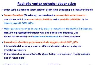
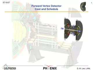
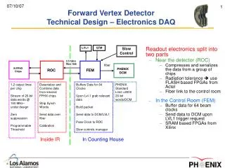
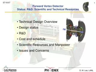
Forward Vertex Detector Overview. Technical Design Overview Design status. Forward Vertex Detector Technical Design – Specifications. Cover the Muon Spectrometer Acceptance – both Arms (10-35 deg) Full Azimuthal coverage – hermetic DCA resolution < 200 µ m at 5 GeV

E N D
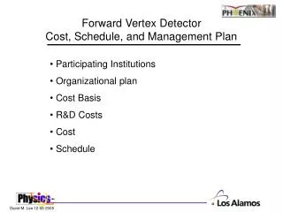
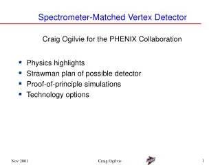
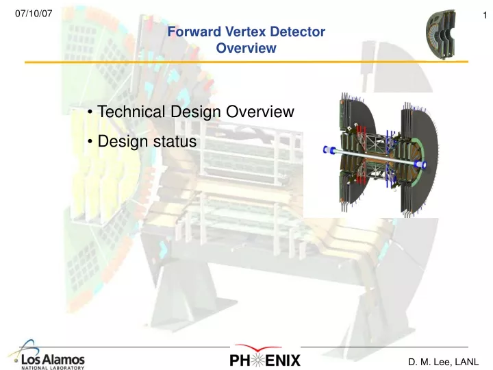
Forward Vertex DetectorOverview • Technical Design Overview • Design status
Forward Vertex DetectorTechnical Design – Specifications • Cover the Muon Spectrometer Acceptance – both Arms (10-35 deg) • Full Azimuthal coverage – hermetic • DCA resolution < 200 µm at 5 GeV • ≥ 3 space points / track • Maximum Radiation Length < 2.4% • Survive 10 year integrated dose = 200k Rad • Low Occupancy in Au – Au Central < 10.0% • Co-exist with barrel VTX • Compatible with PHENIX DAQ
Forward Vertex DetectorTechnical Design – Mechanical “Big Wheel” Location for all readout electronics Combined VTX + FVTX without outer enclosure FVTX
Forward Vertex DetectorTechnical Design – Mechanical Each Endcap 4 hermetic disks, z=18.5 – 38 cm 48 wedge segments per disk ( 7.5 deg) Inner disk radius = 3.5 cm (4.5 cm active) Outer disk radius = 17 cm 75 micron strips, 550,000 strips/endcap Total power load of disks = 50 W each Power load of Readout cards= 450 W in big wheel Room temperature operation
Forward Vertex DetectorTechnical Design – Mechanical Mechanical Integration with the Barrel VTX Fully integrated model
Backplane HDI Detector FPHX Chips Rigid, thermally conductive epoxy Rigid epoxy Forward Vertex DetectorTechnical Design – Wedge Connectors for extension cables Screw (nylon) HDI Pin hole (for alignment) Detector FPIX Chips (26, 13 ea. side) Backplane (0.76mm graphite fiber composite) All bonded with rigid epoxies Screw (nylon) Pin hole (for alignment)
HDI Sensor HDI FPHX Chips (13 per column) Forward Vertex DetectorFVTX Sensor • Sensor • 2 columns of strips • 1664 strips per column • strip length 2.8 to 11.2 mm • 75 µm spacing • 48 wedges per disk (7.5˚/sensor, ~15˚/wedge) • 0.5 mm overlap with adjacent wedges • FPHX Chip • 1 column readout • 128 channels • ~ 70 µm channel spacing • Dimensions –9mm x 1.2 mm Mini-strips are oriented to approximate an arc
Sensor layoutR&D prototyping design Zoom in … one FPHX chip Thickness 300 µm Doping of starting material n type Resistivity 2-5 K-cm Wafer diameter 6 “ preferred Passivation SiO or SiN bonding pads testing pads (both staged) Guard ring Vaclav Vrba, Prague Dicing edge
SensorR&D A real prototype Vaclav Vrba, Prague
HDI Stack Up GND Signal Signal Power Forward Vertex DetectorHDI-High Density Interconnect kapton • High Density Interconnect (HDI) – kapton flat cable to transfer data from the chip to the read-out electronics • 176 μm thick • 4 copper planes (ground, power, 2ea signal), 5 Kapton films, 8 glue layers glue glue kapton glue glue kapton glue glue kapton glue glue kapton HDI • HDI trace count • 2 R/O lines x LVDS pair x 26 chips 104 • 4 Download and Reset lines 4 • 2 Clocks x LVDS pair 4 • 1 Calibration line 1 • 113
Wedge R&D AnalysisTemperature & Stress Max deflection 10.4μm • Warmest FPHX Chip is 5.3ºC Warmer than Back Edge of Backplane Min Tº = 15ºC Max Tº = 20.3ºC Warmest ROC Zero deflection (boundary conditions) 3-D Temperature Contour 3-D Distortion Contour
Single piece plastic insert for screws and pins Standoff plate Thermally conductive Silicone Foam core Honeycomb core Plastic inserts for screws and pins Forward Vertex DetectorHalf-Disk Assembly: Details
Max deflection of detector ~8μm Disk-Level R&D Modeling Thermal distortion Distortion due to cooling Fundamental vibration mode: 164 Hz
Cooling hose (silicone) Station 1 Station 2 Station 3 Station 4 Half Cage Assembly Y Al Honeycomb core, C face sheets Z
Liquid Cooling CircuitR&D Outlet plane 4: 10.3°C Outlet plane 2: 10.9°C station 2: ~21.2°C station 4: ~20.6°C Warmest Chip, station 1: ~21.4°C FVTX Outlet: 11.1°C, ~3 psig station 3: ~20.9°C FVTX Inlet: 10°C, ~5 psig Outlet plane 3: 10.6°C
Half Cage AssemblyR&D Drum mode shape (f=137.7 Hz) Gravity Sag (Max = 3.2µm)
VTX+FVTXFinite Element Model R&D First Mode: 38Hz
VTX – FVTX IntegrationThe need began 2 years agoBut we found this 2 months ago Interference!