Download

1 / 54
550 likes | 873 Views
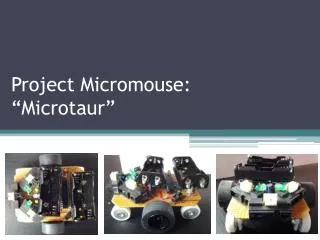
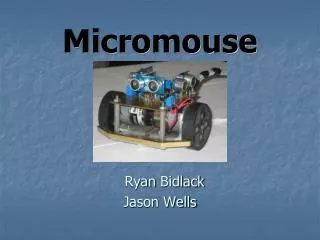
Making of Micromouse. P.Raghavendra Prasad Final Yr EEE. www.raghu.co.nr. INTRODUCTION. Micromouse is an autonomous robot designed to reach the center of an unknown maze in shortest possible time and distance . www.raghu.co.nr. M I C R O C O N T R O L L E R. MOTOR DRIVER.

E N D
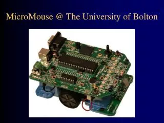
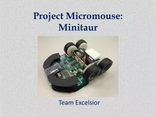
Making of Micromouse P.Raghavendra Prasad Final Yr EEE www.raghu.co.nr
INTRODUCTION Micromouse is an autonomous robot designed to reach the center of an unknown maze in shortest possible time and distance . www.raghu.co.nr
M I C R O C O N T R O L L E R MOTOR DRIVER LEFT MOTOR SENSOR ELECTRONICS SESNSORS RIGHT MOTOR www.raghu.co.nr
Basic components of Micromouse: • Sensors • Motors • Microcontroller • Batteries www.raghu.conr
SENSORS • Your mouse is going to need sensors to tell it about itself and its environment. • These are used to detect the presence or absence of walls and to verify your position in the maze. • They will also be important in ensuring that the mouse maintains an appropriate path without hitting any walls www.raghu.co.nr
Sensors • Commonly used sensors in the field of robotics • IR Digital sensors • IR analog sensors www.raghu.co.nr
IR Digital sensors • Transmitter • IR led connected to 38KHz oscillator • Receiver • TSOP1738 • Advantages • Detects an obstacle at a distance more than 1meter if tuned perfectly. • No ambient light effect. • Easy to use. www.raghu.co.nr
Designing a transmitter : • Use IC 555 in Astable mode • For approximate 50% duty cycle take Ra = 1 k ohm www.raghu.co.nr
IR Analog sensors • Transmitter • IR LED • Receiver • IR Photodiode • Advantages: • Can measure distance up to 15 cm. • Disadvantages: • Responds to IR rays present in ambient light. • Intensity of reflected rays is non-linear with respect to distance of obstacle www.raghu.co.nr
IR Analog sensor www.raghu.co.nr
Modulate IR rays to avoid Ambient light effect : Astable oscillator at frequency greater than 1KHz Transmitter IR led ADC of Micro-controller High pass filter , Cut-off freq more than 300Hz Peak Detector Receiver IR Photodiode obstacle www.raghu.co.nr
High-Pass filter : www.raghu.co.nr
Peak Detector: www.raghu.co.nr
Errors involved in mouse movement : Forward error: Forward errors begins when a mouse is either too close or too far from the wall ahead www.raghu.co.nr
Errors involved in mouse movement : Offset error : Offset errors, which happens often, is caused by being too far to the left or to the right as you pass through a cell www.raghu.co.nr
Errors involved in mouse movement : Heading error: Heading error is known as pointing at walls rather than down the middle of the cell www.raghu.co.nr
Commonly used Sensor arrangement : • Top Down • Side Looking www.raghu.co.nr SENSORS
Top Down www.raghu.co.nr
Side looking sensors : www.raghu.co.nr
Initialize ADC Select ADC channel Start ADC ADC conversion complete N0 Yes Read ADC value Stop www.raghu.co.nr
Side looking Sample code for ADC conversion in AVR controllers : Unsigned int left_adc; left_adc = adc(0xE0); unsigned int adc(unsigned int temp) { ADMUX = temp; //selects ADC channel ADCSRA |= 0x40; //starts ADC while(conversion_not_over()); //waits till ADC conversion completes ADCSRA |= 0x10; // clears ADIF flag return(ADCH); // returns ADC result } int conversion_not_over(void) { unsigned int temp; temp = ADCSRA; temp = temp & 0x10; // checks for ADIF flag return(!temp); } www.raghu.co.nr
Reducing error using PD controller : Error PD controller Motors www.raghu.co.nr
Error calculating: • If wall is on both sides • err = left_adc – right_adc; • If err is +ve • Mouse is near to left wall and as a correction it has to move towards right wall • If wall is only on leftside • err = left_adc – reff_value; • If err is +ve • Mouse is near to left wall and as a correction it has to move towards right wall • If wall is only on rightside • err = right_adc – reff_value; • If err is +ve • Mouse is near to right wall and as a correction it has to move towards left wall www.raghu.co.nr
Implementing PD controller: • err_d = err – err_past; • adj = err * kp + err_d * kd ; • kp is proportional controller constant • kd is derivative controller constant • The value of adj is used to either speed up or speed down one of the wheel . www.raghu.co.nr
DC Motor • DC Motors are small, inexpensive and powerful motors used widely. • These are widely used in robotics for their small size and high energy out. • A typical DC motor operates at speeds that are far too high speed to be useful, and torque that are far too low. • Gear reduction is the standard method by which a motor is made useful . • Gear’s reduce the speed of motor and increases the torque www.raghu.co.nr
Choosing a DC Motor • DC Motor with Gear head • Operating voltage 12V • Speed • Depends on our application • Some available speeds in market • 30 RPM • 60 RPM • 100 RPM • 150 RPM • 350 RPM • 1000 RPM www.raghu.co.nr
Drive basics of DC Motor www.raghu.co.nr
Bi-Direction control of DC Motor H-Bridge Ckt using transistors for bidirectional driving of DC motor www.raghu.co.nr
H-Bridges in IC’s to reduce the drive circuit complexity • The most commonly used H-Bridges are L293D and • L298 • L293D has maximum current rating of 600ma • L298 has maximum current rating of 2A • Both has 2 H-Bridges in them • These are designed to drive inductive loads such as • relays, solenoids • Can be used to drive 2 DC motors or 1 stepper motor www.raghu.co.nr
STEPPER MOTOR • STEPPER MOTOR is a brushless DC motor whose rotor rotates in discrete angular increments when its stator windings are energized in a programmed manner. • Rotation occurs because of magnetic interaction between rotor poles and poles of sequentially energized stator windings. • The rotor has no electrical windings, but has salient and/or magnetized poles. www.raghu.co.nr
5 – Lead stepper 4 – Lead stepper 6 – Lead stepper 8 – Lead stepper www.raghu.co.nr
Full Step driving of Stepper Motor Full step wave drive www.raghu.co.in
Full Step driving of Stepper Motor Full step 2 phases active www.raghu.co.in
Half Step driving of stepper motor www.raghu.co.nr
Choosing a Stepper motor • 12 V or 5 V operating voltage • 1.8 degree step • 6 Lead • 250 to 500 ma of current • or • Coil resistance of 20 ohms to 40 ohms • Size and shape depends on application • In most of the robotics cube shaped motors are preferred with frame size of 3.9 to 4 cm www.raghu.co.nr
Commonly used IC’s for driving Stepper motor • ULN2803 • It has 8 channels • It channel has maximum current rating of 500ma • can be used to drive 2 unipolar stepper motors • L293d • L297 & L298 • UDN2916 www.raghu.co.nr
ULN2803 www.raghu.co.nr
Bi – Polar driving of Stepper Motor www.raghu.co.nr
5 – Lead stepper 4 – Lead stepper 6 – Lead stepper 8 – Lead stepper www.raghu.co.nr
Sample program for(p=0;p<=20;p++) { PORTD=0xA9; delay(65); PORTD=0x65; delay(65); PORTD=0x56; delay(65); PORTD=0x9A; delay(65); } void delay(unsigned int m) { unsigned int n; while(m--) for(n=0;n<=100;n++); } • With this SW Steppers can’t be controlled individually www.raghu.co.nr
SW for steppers : • Use timers to create delay. • Use Clear Timer on Compare match • or • Normal Mode www.raghu.co.nr
Initialize timer Interrupt routine Give Pulse to stepper Start Timer Is Stepper target reached Update Output compare register No Wait Reti Yes Stop timer www.raghu.co.nr
Chopper Driving: • For better performance of Steppers they should be over driven and current should be limited . • For example a 5 V 500ma motor can be driven at more than 15V but current in the coil should be limited to approximately 500ma . www.raghu.co.nr
Methods of current limiting : • Traditional method of using a resistor of appropriate power in series with common terminal. • This method is not recommended as there will be huge power wasted in the series resistor. www.raghu.co.nr