Download
1 / 13
130 likes | 353 Views
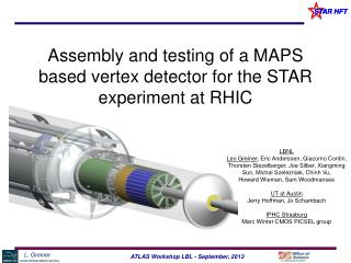
The STAR-PXL electronics system. LBNL Leo Greiner , Eric Anderssen , Thorsten Stezelberger , Joe Silber, Xiangming Sun, Michal Szelezniak , Chinh Vu, Howard Wieman UTA Jerry Hoffman, Jo Schambach IPHC Strasburg Marc Winter CMOS group. Talk Outline.

E N D
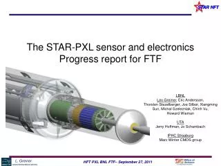
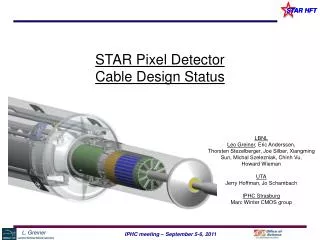
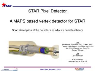
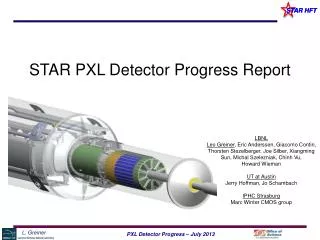
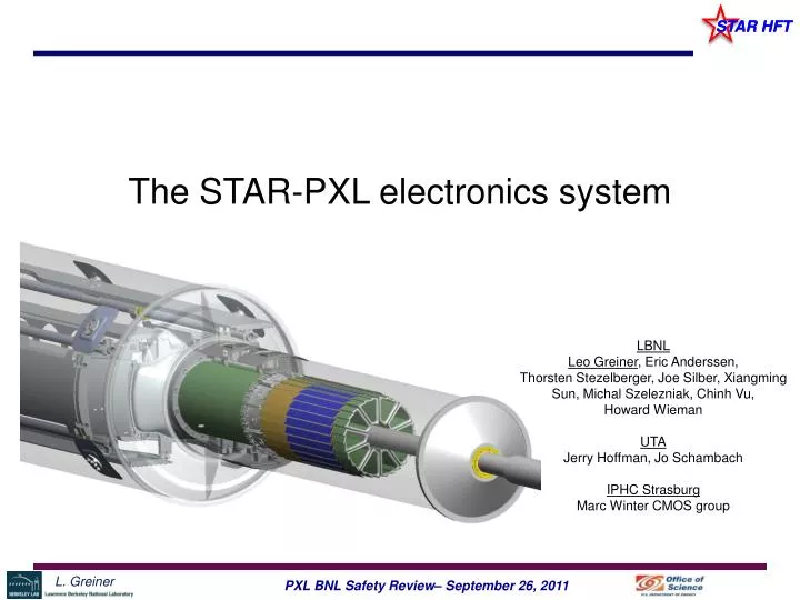
The STAR-PXL electronics system LBNL Leo Greiner, Eric Anderssen, Thorsten Stezelberger, Joe Silber, Xiangming Sun, Michal Szelezniak, Chinh Vu, Howard Wieman UTA Jerry Hoffman, Jo Schambach IPHC Strasburg Marc Winter CMOS group
Talk Outline • Hardware architecture of RDO system • Electronic structure of PXL system • Sensors and ladder cable • Mass termination board (MTB) • RDO board • Grounding, power and signal paths • Cooling System
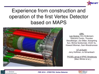
Aluminum conductor Ladder Flex Cable PXL Detector Mechanical Design Mechanical support with kinematic mounts (insertion side) carbon fiber sector tubes (~ 200µm thick) Insertion from one side 2 layers 5 sectors / half (10 sectors total) 4 ladders/sector Ladder with 10 MAPS sensors (~ 2×2 cm each) 20 cm
PXL Detector Basic Unit (RDO) 6 m (24 AWG TP) 2 m (42 AWG TP) Mass Termination Board + latch-up protected power daughter-card Clk, config, data Clk, config, data, power RDO motherboard w/ Xilinx FPGA RDO PC with DDL link to RDO board 100 m (fiber optic) PXL built events • Highly parallel system • 4 ladders per sector • 1 Mass Termination Board (MTB) per sector • 1 sector per RDO board • 10 RDO boards in the PXL system
PXL RDO Architecture (1 sector) i/o USB ADC SIU FPGA DAQ RDO PCs SRAM Power Supplies Control PCs Trigger Ladder x 4 RDO board x 1 fiber Unified Development Platform Sensor testing Probe testing LU prot. power Black – cfg, ctl, clk. path Blue – data path Red – power / gnd path Green – testing path MTB x 1
Aluminum conductor Ladder Flex Cable Sensors and Ladder Cable MAPS Sensor Sensor dissipation is ~540mW/sensor Power = 3.0V @ 180mA / sensor Ladder power is latch-up (over current) protected by a regulator circuit on the MTB. This circuit has been extensively tested in our LU testing program. http://rnc.lbl.gov/hft/hardware/docs/latchup/LU_POWER_PCB.pdf
Mass Termination Board Prototype board Buffers signals and control Generates LU protected power for ladders Polyfuses on input side of power Board power is LU protected
Production Prototype RDO board SIU VME P1 Daughter Card USB Ladder Data Connectors JTAG ~4A / RDO board Xilinx Virtex-6 FPGA
Production System Design We will use the 9U VME physical standard for RDO motherboards. (Not the electrical standard) 1 standard VME crate with P1 backplane for STAR TCD distribution. Data from sectors arrives via cables plugging into the back of the RDO boards in the P2/P3 locations. STAR TCD • System consists of: • 10 double wide 9U VME RDO boards • 1 single wide 6U VME TCD board SIU SIU SIU SIU SIU SIU SIU SIU SIU SIU Daughter Card Daughter Card Daughter Card Daughter Card Daughter Card Daughter Card Daughter Card Daughter Card Daughter Card Daughter Card 356 M pixel readout in a single 9U VME crate USB USB USB USB USB USB USB USB USB USB JTAG JTAG JTAG JTAG JTAG JTAG JTAG JTAG JTAG JTAG Standard 21 slot 9U VME crate
Cabling Signal & control Ladders to MTB AWG 42 (WireTronic part # 2-42QPN-05) MTB to PP to RDO Board Scsi Cable - VHDCI-68 male to HD68 male - U320 LVD/SE/HVD commercial cable UL type CMG Power PS to PP 10/4 HTC Cu Power cable PP to MTB 12 AWG hookup wire MTB to ladders 40 AWG transformer wire – multiple strands
Cooling system for PXL We have not completed a detailed design for this system. The parts are based on a successful cooling test done at LBNL. The airflow monitors will be interlocked with the sensor power. Dust Collector PXL Conditioner
PXL RDO Summary • MTB and RDO boards are protected with polyfuses. • Ladders are over-current protected with LU power modules. • Power supplies are soft grounded are the STAR racks. • Carbon fiber support structures are conductive and grounded. • RDO boards are powered by a STAR standard VME crate.