Download
1 / 24
240 likes | 375 Views
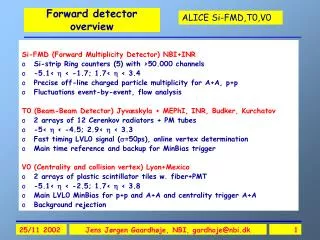
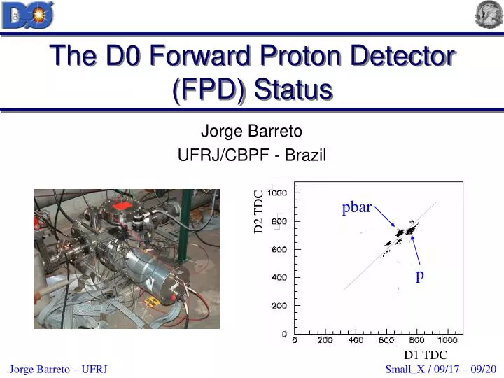
The D0 Forward Proton Detector (FPD) Status. pbar. Jorge Barreto UFRJ/CBPF - Brazil. D2 TDC. p. D1 TDC. Forward Proton Detector Layout. p. 9 momentum spectrometers comprised of 18 Roman Pots

E N D
The D0 Forward Proton Detector (FPD) Status pbar Jorge Barreto UFRJ/CBPF - Brazil D2 TDC p D1 TDC
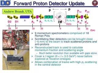
Forward Proton Detector Layout p • 9 momentum spectrometers comprised of 18 Roman Pots • Scintillating fiber detectors can be brought close (~10 mm) to the beam to track scattered protons and anti-protons • Reconstructed track is used to calculate momentum fraction and scattering angle • Much better resolution than available with gaps alone • Cover a t region (0 < t < 4.5 GeV2) where the high t range was never before explored at Tevatron energies • Allows combination of tracks with high-pT scattering in the central detector p P1U P2O Q4 Q3 Q2 Q2 S D Q3 Q4 S A1 D1 A2 D2 P1D P2I Veto 57 59 23 0 33 23 33 Z(m)
Castle Status • All 6 castles with 18 Roman pots comprising the FPD were constructed in Brazil, installed in the Tevatron in fall of 2000, and have been functioning as designed. A1 Quadrupole castle installed in the beam line.
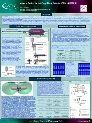
FPD Detector Setup • 6 planes per detector in 3 frames and a trigger scintillator • U and V at 45 degrees to X, 90 degrees to each other • U and V planes have 20 fibers, X planes have 16 fibers • Planes in a frame offset by ~2/3 fiber • Each channel filled with four fibers • 2 detectors in a spectrometer 17.39 mm V’ V Trigger X’ X U’ U 17.39 mm 1 mm 0.8 mm 3.2 mm
Detector Construction At the University of Texas, Arlington (UTA), scintillating and optical fibers were spliced and inserted into the detector frames. The cartridge bottom containing the detector is installed in the Roman pot and then the cartridge top with PMT’s is attached.
Combination of fibers in a frame determine a segment Need two out of three possible segments to get a hit U/V, U/X, V/X Can reconstruct an x and y Can also get an x directly from the x segment Require a hit in both detectors of spectrometer Segments to Hits y x 10 Segments (270 m) v u x
Detector Status • 10 of the 18 Roman pots have been fully instrumented with detectors • Funds to add detectors to the remainder of the pots have recently been obtained • from NSF. • During the shutdown • (Sep-Nov. 2003), the final eight • detectors and associated readout • electronics are being installed. P2 Quadrupole castle with up and down detectors installed
Pot Motion Software Pot motion is controlled in the DØ Control Room via a Python program that uses the DØ online system to send commands to the step motors in the tunnel. The software is reliable and has been tested extensively. It has many safeguards to protect against accidental insertion of the pots into the beam.
Operations • Currently FPD pots are inserted in every store • Commissioning integrated FPD • Have some dedicated FPD triggers, more when TM operational • Working towards automated pot insertion
Stand-alone DAQ – Phase 1 • In phase I we used a stand-alone DAQ (2000 engineering run). • We build the trigger with NIM logic using • signals given by our trigger PMT’s, veto • counters, DØ clock, and the luminosity monitor. • If the event satisfies the trigger requirements, the CAMAC module will process the signal given by the MAPMT’s. • With this configuration we can read the fiber information of only two detectors, although all the trigger scintillators are available for triggering.
Quadrupole Elastic Data LM VC Halo Early Hits A1U A2U Pbar P P2D P1D In-time hits in AU-PD detectors, no early time hits, or LM or veto counter hits • Over 1 million elastic trigger events taken with stand-alone DAQ • About 1% pass multiplicity cuts • Multiplicity cuts used for ease of reconstruction and to remove halo spray background
Initial Reconstruction Reconstructed Y (mm) beam P1D X (mm) DØ Preliminary Y (mm) P2D beam =p/p should peak at 0 for elastic events!! Dead Fibers due to cables that have since been fixed X (mm)
Spectrometer Alignment P1D x vs. P2D x (mm) P1D y vs. P2D y (mm) • Good correlation in hits between detectors of the same spectrometer but shifted from kinematic expectations • 3mm in x and 1 mm in y DØ Preliminary
Elastic Data Distributions After alignment correction, x peaks at 0(as expected for elastics) The t distribution has a minimum of 0.8 GeV2; tmin is determined by how close the pots are from the beam, shape is in rough agreement with expected angular acceptance from MC. FPD is also a tool helping BD Before alignment After alignment Gaussian fit t distribution DØ Preliminary
TDC Timing from Trigger PMTs tp – tp = 18ns TOF: 197ns 190ns From TDCs : 18ns = (396ns – L1/c) – L1/c 4ns = (396ns – L2/c) – L2/c L1 = 56.7 m; L2 = 58.8 m DØ Preliminary tp – tp = 4ns Tevatron Lattice: L1 = 56.5m; L2 = 58.7m
TDC Resolution • Can reject proton halo at dipoles using TDC timing • Can see bunch structure of both proton and antiproton beam • 1ns ~ 4 TDC channels pbar D2 TDC p DØ Preliminary D1 TDC
Standalone Readout vs. AFE Readout • Standalone Readout • No TDC cut • such cut removes lower correlation in y plot • Diffracted pbars fall in upper correlation of y plot • Uses a trigger based on particles passing through trigger scintillators at detector locations x1 y1 D0 Preliminary x2 y2 • AFE readout • Uses trigger: • one jet with 25GeV and North luminosity counters not firing • This trigger suppresses the halo band • Similar correlations y1 x1 D0 Preliminary x2 y2
Dipole Diffraction Results - Alignment All units in mm Y1 Y2 • Raw data sample has 4640 events • Reconstruction of ~50% of events • Hit patterns: Misalignment? • Hit correlations: pbar halo? • Poor and t distributions X1 Beam X2 X1 Y1 D0 Preliminary Y2 X2 t (GeV2)
Dipole Diffraction Results - II Y1 Y2 X1 X2 X1 Y2 MC Data Y2 X2 t (GeV2) All units in mm • Shifts ΔY1= ΔY2=+2mm • Cut the pbar blob (X2 > -14mm) • Fair agreement between MC and Data • More realistic and t distributions • Allow to study vs t correlation D0 Preliminary
Dipole Diffraction Results - III Geometrical Acceptance 14σ Data Flat-t distribution 0.08 D0 Preliminary 0.06 D0 Preliminary 0.04 0.02 0. |t| (GeV2 ) |t| (GeV2 )
DØ Run II Diffractive Topics E Soft Diffraction and Elastic Scattering: Inclusive Single Diffraction Elastic scattering (t dependence) Total Cross Section Centauro Search Inclusive double pomeron Search for glueballs/exotics Hard Diffraction: Diffractive jet Diffractive b,c ,t , Higgs Diffractive W/Z Diffractive photon Other hard diffractive topics Double Pomeron + jets Other Hard Double Pomeron topics Rapidity Gaps: Central gaps+jets Double pomeron with gaps Gap tags vs. proton tags Topics in RED were studied with gaps only in Run I <100 W boson events in Run I, >1000 tagged events expected in Run II
Summary and Future Plans • Run II analysis still in early stages • Early FPD stand-alone analysis shows that detectors work • FPD now integrated into DØ readout • Commissioning of FPD and trigger in progress • Gap results in Run II not yet approved • Full 18 pot FPD will start taking data after shutdown (12/03) • Tune in next year for first FPD physics results