Download
1 / 23
230 likes | 348 Views
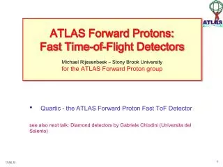
ATLAS Forward Proton Electronics. Andrew Brandt, University of Texas at Arlington. AFP concept: adds new ATLAS sub-detectors at 220 and 420 m upstream and downstream of central detector to precisely measure the scattered protons to complement ATLAS discovery program.

E N D
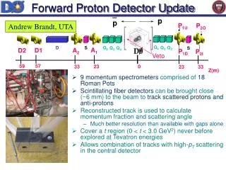
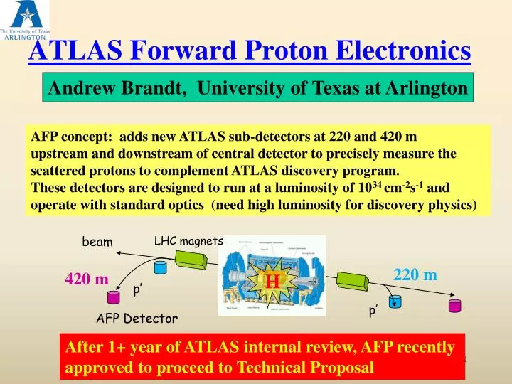
ATLAS Forward Proton Electronics Andrew Brandt, University of Texas at Arlington AFP concept: adds new ATLAS sub-detectors at 220 and 420 m upstream and downstream of central detector to precisely measure the scattered protons to complement ATLAS discovery program. These detectors are designed to run at a luminosity of 1034 cm-2s-1 and operate with standard optics (need high luminosity for discovery physics) beam LHC magnets H p’ 220 m 420 m p’ AFP Detector After 1+ year of ATLAS internal review, AFP recently approved to proceed to Technical Proposal
What is AFP? • Impressive array of rad-hard edgeless 3D silicon with resolution • ~10 m, 1rad • 2) New Connection Cryostat at 420m • 3) “Hamburg Beam Pipe” instead of Roman Pots • 4) Timing detectors with ~10 ps resolution for overlap background • rejection Ex: Two b-jets from one interaction and two protons from another Use time difference between protons to measure z-vertex and compare with tracking z-vertex measured with silicon detector (x20 rejection with 10 ps timing resolution) Andrew Brandt Clermont-Ferrand
What does AFP Provide? • Mass and rapidity of centrally system • where 1,2 are the fractional momentum loss of the protons • Mass resolution of 3-5 GeVper event Acceptance >40% for wide range of resonance mass Combination of 220 and 420 is key to physics reach! 420- 420 420- 220 220- 220 Allows ATLAS to use LHC as a tunable s glu-glu or collider while simultaneously pursuing standard ATLAS physics program
Timing System Requirements • 10 ps or better resolution • Robust: capable of operating with little or no intervention in radiation environment (tunnel) • ~100% efficiency • Acceptance over full range of proton x+y • Segmented (multi-proton timing) • High rate capability • Two main options: 1) one very precise measurement (GASTOF) 2) multiple less precise measurements (QUARTIC) Andrew Brandt Clermont-Ferrand
QUARTIC proton UTA, Alberta, Stonybrook, FNAL photons 4x8 array of 5-6 mm2 fused silica bars Only need a 40 ps measurement if you can do it 16 times: 2 detectors with 8 bars each, with about 10 pe’s per bar • Multiple measurements with “modest” resolution simplifies requirements in all phases of system • 1) We have a readout solution for this option (subject of this talk) • We can have a several meter cable run to a lower radiation area where electronics will be located • 3) Segmentation is natural for this type of detector
MCP-PMT Requirements Excellent time resolution: 20 ps or better for 10 pe’s High rate capability: Imax= 3 A/cm2 Long Lifetime: Q= 30 C/cm2/year at 400 nm Multi anode: pixel size of ~6 mm x 6mm Tube Size: 40 mm round, 1 or 2 inch square Pore Size: In our experience 10 m or better We need 4/5 of tough requirements (only thing we don’t need is large area!)
Components of AFP Fast Timing System HPTDC board (Alberta) Louvain Custom CFD (LCFD) Mini-circuits ZX60 3 GHZ or equivalent QUARTIC: Photonis planacon (10 m pore 8x8) or 40 mm Photek MCP-PMT Reference Timing HV/LV Stonybrook AMP to HPTDC Ref. time SLAC +LLNL <1 ps ! Opto-modules/ ROD UTA QUARTIC/PMT Development Manchester/UCL
Fourier Transform of Signal Lecroy 8620A Wavemaster 6 GHz 20 Gs/s 10 m planacon, 40 pe’s -whole signal is in first GHz -scope bandwidth is 6 GHz -cell phone/wireless noise contributions visible -we use high bandwidth amp because of low noise and then add filtering. A 1 GHz low noise amplifier would likely be preferable, but we couldn’t find one so we filter (1.5 GHz filter helps a little, 1 GHz starts to cut into signal degrade performance) 1 GHz Andrew Brandt Clermont-Ferrand
LCFD ZX60 3 GHz amplifier (we use pairs of 3,4, 8 GHz amps in different combinations to control total amplification) • LCFD (Louvain Constant • Fraction Discriminator) • 12 channel NIM unit • mini-module approach • tuned to PMT rise time • Excellent performance : <10 ps resolution for 4 or more pe’s Remote control for threshold Andrew Brandt Clermont-Ferrand
LCFD Performance • Use large light signal to get narrow pulse width and attenuators to evaluate LCFD “sweet spot” • LCFD prefers >200 mV • Note our scope resolution is about 2 ps (measured using splitter after LCFD) 100 pe’s V
LCFD Resolution Pulses are amplified such that the mean pulse height is 500 mV (Note: must optimize every measurement this way—any time you vary the pulse height by changing HV or number of PE’s must check that you are still in the sweet spot of LCFD) Andrew Brandt Clermont-Ferrand
LCFD Performance Using attenuators can measure the time shift as a function of pulse height for a fixed number of pe’s, and determine a residual correction factor as a function of pulse height, which we can apply for any number of pe’s: but LCFD is so good this is not really necessary Andrew Brandt Clermont-Ferrand V ps
Alberta HPTDC Board • Targeting ~20 ps RMS resolution; • (STAR TOF reported 24 ps, ALICE TOF reported 20 ps, Ref: 1,2) • 8 differential LVPECL input channels ; • 1 HPTDC (v1.3) chip from CERN in Very High Resolution Mode; • Altera Cyclone2 FPGA, Cypress USB chip for local debug; • Serial LVDS link to connect to the main RODs (ATLAS Readout) • Both USB and the Serial LVDS link provide timing and control signals to HPTDC • Ref 1: J. Schambach, “Proposed STAR time of flight readout electronics and DAQ”, Computing in High Energy and Nuclear Physics, 24-28, March 2003, La Jolla, California. • Ref 2: P. Antonioli, “A 20 ps TDC readout module for the ALICE time of flight system: design and test results”. 9th Workshop on Electronics for LHC Experiments, Amsterdam, The Netherlands, 29 Sep - 3 Oct 2003, pp.311-315 Jim Pinfold Shengli Liu Andrew Brandt Clermont-Ferrand
Alberta HPTDC board 12 ps resolution with pulser including non-linearity corrections. Successfully tested at UTA laser test stand with laser/10 m tube/ZX60 amp/LCFD 13.7 ps with split LCFD signal Andrew Brandt Clermont-Ferrand
QUARTIC HPTDC Buffering Concern: During discussions at Photek we learned that occupancy of HPTDC would be a problem for >2 MHz (this is in the manual, but who reads manuals?) Study used HPTDC Verilog model & measurement, simulation details: • At high luminosity, the hottest pixel would see a rate of 10-15 MHz • The minimum spacing between triggers is 25 ns • ATLAS L1 trigger rate 100 KHz, with a trigger latency of 2.5 ms; Andrew Brandt Clermont-Ferrand
QUARTIC HPTDC Buffering Andrew Brandt Clermont-Ferrand
BufferingResults – Loss Rate Loss rate in channel buffer for Logic core clock = 40MHz Loss rate in channel buffer for Logic core clock = 80MHz \ Only input channel 0 is connected (4 useful channels/ chip instead of 8) Andrew Brandt Clermont-Ferrand
Buffering Test Results • Standard version of HPTDC chip works with a core clock frequency up to 80 MHz • A special speed graded version of HPTDC chip could work with core clock of 160 MHz. • RMS resolution is not affected when running with 80MHz clock. • Occupancy at trigger and readout FIFO’s is low enough • Modest increase in power consumption Andrew Brandt Clermont-Ferrand
Reference Timing Reference timing is needed to connect two arms ~1km apart; what we want is TL-TR, what we measure is (TL-Tref)-(TR-Tref), so need small jitter in Tref This setup has been tested to give 150 fs with 100m cable (1km cable isexpensive!) The reference system uses a phase lock loop to maintain a constant number of wavelengths in a 100m cable. This synchronizes the phase of the RF at each end of the cable. A voltage controlled oscillator (VCO) launches a signal down the cable where it is reflected and sent back. The returned signal is then interfered with an external RF reference to synchronize it with the reference. At the end of the 100m cable the signal is sampled with a directional coupler which mixes the signal to produce a DC level. That DC level is fed back to the VCO to maintain a constant number of wavelengths in the cable. Andrew Brandt Clermont-Ferrand
Ref. Timing Rate Reduction • Concern: integrating reference time into DAQ • Planned to dedicate one channel/chip to reference time signal • However reference time needs to be available every 25 ns: 40 MHz (too high!) • Actually we only need reference time for good events! • 1) Form a trigger based on multiplicity of CFD signals in one row -example if at least 4/8 bars have a signal 2) Only send CFD signals to HPTDC board if trigger is satisfied 3) Trigger reference time signal as well, so a chip will have 4 inputs: three bars in the row where trigger was satisfied, and the ref time signal corresponding to that row 4) Also keep some prescaled signals for monitoring • Select the reference timing edges and CFD signals to HPTDC board by following conditions: • CFD signals arrive within 2 ns window of “Enable” ( 2ns corresponds to full vertex coverage at ATLAS +/- 30 cm (expect all events in a 2 ns window) • A predefined multiplicity coincidence “trigger” be met for above CFD signals; • The reference edges related to above CFD signals are passed. Andrew Brandt Clermont-Ferrand
L1 TRIGGER • The Trigger formed in previous slide for controlling reference time rates can also be used for a L1 Trigger! • The total number of trigger bits we send back to ATLAS for L1 is a balance between: • Optimal binning to give the lowest background trigger rate (when combined with jet information from calorimeter) • The practical limits on the number of cable connections we can make, serial transmission schemes, and CTP input availability. • The simplest scheme involves sending four bits directly over individual cables (low, intermediate, high, very high mass, for example). • Large diameter air core cables are required to minimize the cable delay due to latency concerns.
Conclusions • We have developed a fast timing system for AFP that seems to be capable of ~10 ps resolution • Test beam is planned for this year with an 8-channel prototype system from the detector through to ATLAS readout. • Work in progress: • 1) final optimization of detector (looking into quartz fibers—could lower maximum rate by 2-3 by more sensible binning) • 2) developing and testing long-life MCP-PMT • 3) evaluating radiation tolerance of all components and upgrading as needed Andrew Brandt Clermont-Ferrand
Bonus Session on MCP-PMT LifetimeSatuday Jan. 30 9:00-11:30 Comments/Questions/Suggestions: Please see Andrew Brandt (brandta@uta.edu)