Download
1 / 13
130 likes | 316 Views
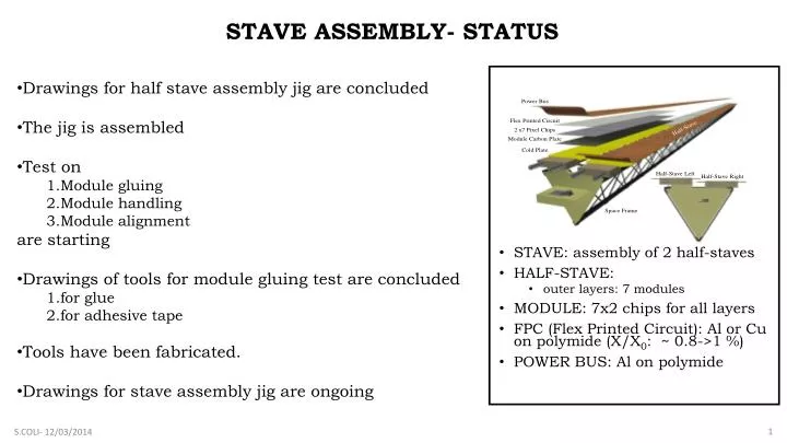
STAVE ASSEMBLY- STATUS. Drawings for half stave assembly jig are concluded The jig is assembled Test on Module gluing Module handling Module alignment are starting Drawings of tools for module gluing test are concluded for glue for adhesive tape Tools have been fabricated.

E N D
STAVE ASSEMBLY- STATUS • Drawings for half stave assembly jig are concluded • The jig is assembled • Test on • Module gluing • Module handling • Module alignment are starting • Drawings of tools for module gluing test are concluded • for glue • for adhesive tape • Tools have been fabricated. • Drawings for stave assembly jig are ongoing • STAVE: assembly of 2 half-staves • HALF-STAVE: • outer layers: 7 modules • MODULE: 7x2 chips for all layers • FPC (Flex Printed Circuit): Al or Cu on polymide (X/X0: ~ 0.8->1 %) • POWER BUS: Al on polymide S.COLI- 12/03/2014
HALF STAVE ASSEMBLY JIG • The base and rails: to put the module in position • The alignment station: to handling and aline the modules • The module box: to store, carry and prealign the modules • The removable base: to accomodate the coldplate, to interconnect the modules and to position the BUS cable ALIGNMENT STATION REMOVABLE BASE MODULE BOX BASE and RAILS S.COLI- 12/03/2014
PROCEDURE FOR THE HALF STAVE ASSEMBLY (1) • The glue (or adhesive tape is spread) • The cold plate is put in position by two pins and taken by vacuum on the removable base Pin for cold plate positioning Cold plate in taken position by vacuum S.COLI- 12/03/2014
PROCEDURE FOR THE HALF STAVE ASSEMBLY (2) • With an alignment station the modules are taken from the box and positioned on the cold plate under a measuring machine. Last module positioning • The base holding the aligned modules glued onto the cold plate can be removed for Module interconnection and BUS positioning module First module positioning Six module aligned Second module in the box ready to be aligned S.COLI- 12/03/2014
HALF STAVE ASSEMBLY JIG ALIGNMENT STATION REMOVABLE BASE MODULE BOX • The jig is completed and assembled under the Mytutoyo measuring machine. It will be used for: • Module handling test • Module alignment test • Half stave assembly BASE and RAILS S.COLI- 12/03/2014
FIRST HALF STAVE PROTOTYPE-FIRST DECISIONS OPEN POINTS on JAN 2014: Module with carbon plate or not (?) Adhesive tape or glue (?) between cold plate and modules. Module marker on chips visible through FPC or placed on FPC (?) Module box definition Mytutoyo or Poli measuring machine (?).[The base is removable to cover the 1,5m stroke in case we use the Mytutoyo measuring machine]. • For the FIRST HALF STAVE PROTOTYPE: • Modules without carbon plate • Glue will be used, but test with adhesive tape will be done. • Module marker are on FPC for first dummy modules, but then the marker will be on chips visible through FPC. • The Module box has been defined and prototypes are on going • Mytutoyo measuring machine will be used. S.COLI- 12/03/2014
TEST ON MODULE GLUING TEST Tools for module gluing test with glue and adhesive tape. Masks to use both solutions are in fabrication First test with mask used by BARI group S.COLI- 12/03/2014
TEST ON MODULE HANDLING MODULE SYSTEMS [CAGLIARI] Suction cups springs S.COLI- 12/03/2014
TEST ON MODULE MODULE HANDLING and MODULE ALIGNMENT [with Cagliari] REFERENCE POINTS FPC LAYOUT «dummy-dummyModules!» S.COLI- 12/03/2014
STAVE ASSEMBLY JIG Check the compatibility with masks for the reference points. S.COLI- 12/03/2014
NEXT STEPS • Test on module gluing • Test on adhesive tapes • Test on module handling • Half stave assembly • Verify the compatibility between stave assembly jig and the mask for the positioning of the stave reference points on end wheels. • Foresee the possibility to test the module just after gluing (the detectors are hidden by the cold plate and the FPC). • Conclude drawings for stave assembly jig. S.COLI- 12/03/2014
Simple circuits for soldering tests Cu lines on kapton • Different pad dimensions: • 1,2 x 0,6 mm • 1 x 0,3 mm • Different pad pitch • 0,4 mm • 0,3 mm connection bridge S. Beolè
Pads for interconnection between FPCs • home made kaptonbridges: pads size can be chosen according to chip pad layout kapton flex kapton flex TIN FPC FPC • arrays of SMD resistors (0 W) • 0603 –> W 1-1.6mm L= 2-3.2 mm P=0.5-0.8mm by Michele Sacchetti S. Beolè