Download
1 / 21
210 likes | 368 Views
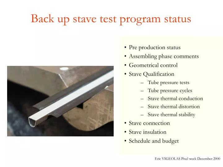
Back up stave test program status. Pre production status Assembling phase comments Geometrical control Stave Qualification Tube pressure tests Tube pressure cycles Stave thermal conduction Stave thermal distortion Stave thermal stability Stave connection Stave insulation

E N D
Back up stave test program status • Pre production status • Assembling phase comments • Geometrical control • Stave Qualification • Tube pressure tests • Tube pressure cycles • Stave thermal conduction • Stave thermal distortion • Stave thermal stability • Stave connection • Stave insulation • Schedule and budget Eric VIGEOLAS Pixel week December 2000
Pre Production status Up to now 5 back up staves was assembled. One have been fully tested for the June mechanical review. One stave was broken during the shipment (but one half was tested to confirm the thermal distortions observed on the previous stave) Three additional stave was manufactured two with an aluminium tube without parylene, the last one was manufactured with Parylene coated tube. This pre production have confirmed that the assembling tools foreseen for the baseline stave was suitable for the Back up stave. Only one additional sequences is needed during the assembling phase (the grease deposition on the tube which take a few minutes). One Sequence in the baseline assembling was changed, the Omega glue deposition. An manual deposition which consist to wet the two wings of the Omega was chosen in order to reduce the amount of Glue. Eric VIGEOLAS Pixel week December 2000
Assembling phase Comments One important result of the stave assembling technique is that due to the pressure applied on the Omega in the gluing phase, the thickness of Omega glue is bellow the expected 0.1mm. 0.1 mm was the nominal grease thickness foreseen. This amount of grease was foreseen to permit to the tube to have a degree of freedom to avoid thermal mismatch. Therefor the tube is in contact with the C-C. The main effects of this observation is: • More thermal deformations due to CTE mismatch, but those deformations are reduced by the use of 5 supports points (presented later), and stays in the requirements • Better thermal efficiency of the cooling pipe • The tube grease layer is less determining is the stave reliability. 0.1mm 0.1mm Pressure applied during the assembling on the Omega The tube is in contact with the C-C Eric VIGEOLAS Pixel week December 2000
Geometrical Control (June stave) Pitch Roll Surface Flatness Each tilted plan of the stave was measured in order to estimate the accuracy reached after the machining and the assembling. The individual plan geometry accuracy is listed in the table bellow. The relative plan location (in R an Z direction ) accuracy is: • Z: ± 50m • R: ± 100m The R location inaccuracy is mainly due to the natural bowing if the stave (composite material, thermal curing…) Eric VIGEOLAS Pixel week December 2000
Geometrical Control (2 November staves) On the new staves received at CPPM the planarity of the Tilted plan was measure: • each plans presented the same “S” shape • The average planarity on 24 plan is 41 m • The sigma is 13 m • The best planarity was 19 m • The worst one was 67 m The main risk of a poor planarity is the difficulty to deposit a module on the surface with the required glue thickness. Two consequences are suspected: • Silicon temperature dispersion if the glue thickness is not controlled • Impossibility to reduce the remaining force to 0 grams during the deposition. Two stave was equipped with Si by using the CPPM module assembling tool. The main results are: • During the thermal test no important temperature dispersion was shown • Remaining forces on Si was existing on a minority of plan (< 100 grams), The consequences of such parameter have to be understood (not yet done). Eric VIGEOLAS Pixel week December 2000
Stave QualificationTube pressure tests F (m) Bars The Aluminium Tube was individually pressurised in order to control it pressure stiffness. The tube flat edge deformation was measured to control eventual remaining distortions. The tube has resist to an internal pressure of 15 bar without remaining deformations. At 4 Bars absolute the tube have a flat face bowing of 15 m. At 8 Bars the flat face bowing is about 25 m. F Eric VIGEOLAS Pixel week December 2000
Stave QualificationTube pressure Cycles 500 Pressure cycles was applied from 1 Bar to 7.5 Bar in order to control if any creep appear. The creep rate observed after the full tests was 0.1% which is negligible. By maintaining the pressure in the tube after the tests no leaks was observed. Further leak tests will be done with He. Eric VIGEOLAS Pixel week December 2000
Stave QualificationStave Thermal Cycles Thermal Chock: -35°C Eric VIGEOLAS Pixel week December 2000
Stave QualificationStave Thermal Cycles The Thermal cycles was performed with full power on the stave (134W), by just switching on and off the power supply. The main variation in the temperature are driven by the inertia of the cooling system (stabilisation of the intern stave pressure, flow rate stabilisation…) than by any effect of the stave thermal conduction changes. Before this test thermal chocks was also applied (power on on one side of the stave and power off on the other side and vice and versa (temperature decrease up to -35°C) + switch off of the cooling with an immediate switch on (temperature goes up to 60°C) ). Moreover during these tests the stave was handle on two points, with allows the mobility of this one. This was the worst conditions (high displacements) to test the reliability of the thermal conduction. Finally this test gave precious informations about the reliability of the NEA123 UV Glue + CGL7018 Grease for the module attachment. Eric VIGEOLAS Pixel week December 2000
Stave QualificationStave Thermal conduction (June stave) The Temperature measured at full power was uniform along the stave. The average Silicon temperature is -12°C. The pressure drop was < 0.05 bar, this involve a very low T along the tube < 2°C. The temperatures measured on the C-C shows a low T in the cross section of the silicon <3°C. The T between the fluid and the silicon is < 12°C The Back up stave meet perfectly the thermal requirements. Tube sensors C-C sensors Eric VIGEOLAS Pixel week December 2000
Stave QualificationStave Configuration (June stave) The stave configuration was as follow: one Pt100 sensor was glued on each silicon(13 sensors),4 Pt100 was glued on the edge of the C-C, Two Pt100 was glued on the tube at the inlet and the outlet. The maximum power applied was 107 Watts on the full stave. This test was done at CERN with C3F8 fluid. Estimations of Silicon temperature by calculations shows that the uniformity of the temperature(T on Si) is < 5°C Estimations of C-C temperature by calculations shows that it is very close to the silicon one (-11°C) Heaters Back thermal sensor on C-C Eric VIGEOLAS Pixel week December 2000
Stave QualificationStave Configuration (November stave) The stave configuration was as follow: one Pt100 sensor was glued on each silicon(13 sensors), Two Pt100 was glued on the tube at the inlet and the outlet. The maximum power applied was 134 Watts on the full stave. This test was done at CERN with C3F8 fluid. Thermal Sensor Heaters Eric VIGEOLAS Pixel week December 2000
Stave QualificationStave thermal conduction test (November stave, before pressure cycles) The Si temperature average values is -11.07 °C on the tilted Si, and -7.05°C on the middle Si. The Pressure drop along the stave is 0.1 Bar. Eric VIGEOLAS Pixel week December 2000
Stave QualificationStave thermal conduction test (November stave, After the Temperature cycles) The Si temperature average values is -12.96 °C on the tilted Si, and -7.34°C on the middle Si. The Pressure drop along the stave is 0.2 Bar. Eric VIGEOLAS Pixel week December 2000
Stave QualificationStave thermal distortion on three aligned points test (June stave) The stave shows an asymmetric behaviour in the two configurations. On side stays within the requirements with a maximal R displacement of 30 m. The other side get out of the specifications. This asymmetry was shown on all the staves measured. Phenomena to be studied.. Two measurements was done in a cold box for a T of 25°C. On of the measurement was done without silicon glued on the stave, the second one with silicon glued on the stave in order to control the module influence on the stave deformation. Eric VIGEOLAS Pixel week December 2000
Stave QualificationStave thermal distortion on five aligned points test (November stave) The stave shows an asymmetric behaviour. On side have a maximal R displacement of 10 m. The other side have a maximal R displacement of 30m . This confirm what was said before about the asymmetry shown on every staves. This measurement was done in a cold box for a T of 25°C. The stave was equipped with Si heaters Eric VIGEOLAS Pixel week December 2000
Stave QualificationStave thermal stability on five aligned points test (November stave) This test was done on half of the stave. This consist of applying a power on Si to maintain a T of 10°C in between The Si and The Coolant. And switch off the power on one and three modules in between two support to control the stave mobility. The Cooling system available at CPPM works at constant cooling power (and not at Temperature constant as for C3F8). This is a worst condition because more parts of the stave will have temperature changes, which involve more displacements. The Maximum displacement after Three modules off was 3 m (indicative value which is inside the tolerance of our CMM) Module3 Module2 Module1 Supports Eric VIGEOLAS Pixel week December 2000
Stave QualificationStave thermal stability on five aligned points test (November stave) Eric VIGEOLAS Pixel week December 2000
Stave Connection Connection project still under study. This subject have took two months of delay due to the use of the induction Power supply by an other experiment. Meanwhile the first Cupro-Nickel Tests pieces was Brazing. The design program is: • Complete the study concerning the Cupro-Nickel • Study the feasibility of an Aluminium pieces brazing Each study is split in several qualifications tests : • Corrosion inspection (visual inspection after a metallurgical polishing) • Pressure test (leak tests coupled with pressure cycles) • Traction and shear tests coupled with He leak tests Remaining studies concerns: • The layout of the piping (designed as close as possible than the baseline one) • The scenarios of the the pipes assembling (staves connection and deconnection). • …. Eric VIGEOLAS Pixel week December 2000
Stave Insulation The stave insulation will be handle by the Parylene deposition on the tube. The insulation resistance is > 20MOhm (limit of our measurement instrument) in between the internal face of the tube (non coated) and the external one. The first stave prototype equipped with a Parylene coated tube was assembled a few weeks ago, and the thermal conduction of this one should be done by January (to verify the effected of the additional thermal resistance due to Paryelene). Eric VIGEOLAS Pixel week December 2000
Schedule and Budget Concerning the additional tasks required for the Back up stave assembling, this have no influence on the schedule of the Baseline stave assembling (the additional tasks take a few minutes). All these tasks will be done at Plyform Which actually is involved in the baseline assembling and which have built the three previous backup staves. The tube delivery is 7 weeks + 4 weeks needed for the Parylene deposition. The tube price plus the Parylene deposition have a price of 50000 ChFr. The additional cost due the the new tasks needed at Plyform is not known. Eric VIGEOLAS Pixel week December 2000