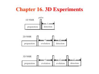
Download
1 / 18
180 likes | 288 Views
TU / e. Organic devices & potential mapping 3D simulations and experiments. Dimitri Charrier , M. Kemerink and R.A.J. Janssen. Agenda. Scanning Kelvin Probe Microscope - why & basics SKPM - Problems Parameter free modeling Conclusions. Introduction. = I, , E, V. = organic device. tip.

E N D
TU/e Organic devices & potential mapping3D simulations and experiments Dimitri Charrier, M. Kemerink and R.A.J. Janssen
Agenda • Scanning Kelvin Probe Microscope - why & basics • SKPM - Problems • Parameter free modeling • Conclusions
Introduction = I, , E, V = organic device
tip Scanning Kelvin probe microscope • Interleave mode • Atomic Force Microscope in tapping mode • Surface potential at Lift Height ZL V Au Au V SiO2
Principle: Force microscope F = force between tip and sample V = tip-sample voltage difference C = capacity between tip and sample Vdc = tip voltage Vac = amplitude voltage Vcpd = contact potential difference Then Vcpd= Vdc For F=0
Experimental results true surface potential V = 10 V Au Au SiO2 Room temperature experiments 3D problem
What is wrong? “the linear drop along the contacts […] “ Vexp < 10 V K.P. Puntambekar, P.V. Pesavento, and C.D. Frisbie Appl. Phys. Lett. 83, 5539 (2003)
What is the real potential? Limited resolutions due to • Capacitive coupling between the tip and the surface SOURCE DRAIN (8 V)
Analytical resolution? APEX CONTRIBUTION IN 2 DIMENSIONS CONE CONTRIBUTION IN 2 DIMENSIONS IT CAN WORK ONLY FOR SYMETRICAL PROBLEMS: APEX + CONE C. Argento and R.H. French, J. Appl. Phys. 80 (1996) 6081
Steps of modeling Software used: COMSOL (Finite Element Method software) + MatLab 3D Drawing in COMSOL Olympus tip: Pt coat 2D simulations done in 2001 by T.S. Gross et al, Ultramicroscopy 87 (2001) 147
Steps of modeling Meshing Zoom on meshing of the tip tip surface Discretization problem: finite amount of tetrahedrons Memory limit with 2 GB of RAM = 370 000 tetrahedrons
Vertical resolution of modeling Scattering due to meshing limitation For obtaining good lateral resolution, first check the vertical resolution For each tip position we calculate the tip-sample force for few tip voltages, then we deduce the surface potential
tip Modeling TRICK source channel drain MOVE THE SURFACE POTENTIAL AND NOT THE TIP OTHERWISE remeshing = scattering
Modeling results - match perfectly Calculation time for ONE curve = 5 min X 3 voltages x 30 points8 hours
Further results = . Vx (Vsd/) Rescaling: Vx (Vsd) Modeling results
Further results Au SiO2 Experimental results
CONCLUSION • We developed a FREE-PARAMETER-FREE SKPM simulation tool, taking into account the lift height influence • Experimental data ≠ real potential due to the capacitive coupling • Experimental response of SKPM is understood • But: so far we cannot ‘invert the system response’
Thanks to The M2N group René Janssen, Martijn Kemerink, Klara Maturova, Alexandre Nardes, Yingxin Liang, Ron Willems, Simon Mathijssen, … TU/e Technical University of Eindhoven The clean-room people Erik-Jan Geluk, Tjibbe de Vries, and Barry Smalbrugge