Download
1 / 19
200 likes | 308 Views
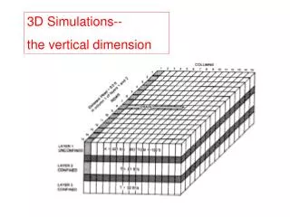
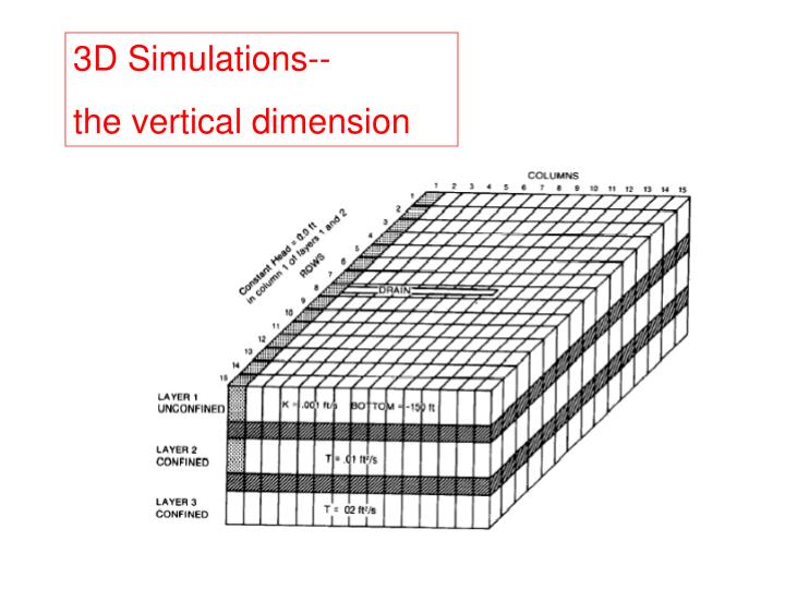
3D Simulations-- the vertical dimension. Representation of hydrogeologic units in MODFLOW88/96. MODFLOW2000. In MODFLOW, vertical flow between layers Is governed by vertical conductance. Review. Horizontal Conductance. Vertical Conductance Terms.

E N D
3D Simulations-- the vertical dimension
Representation of hydrogeologic units in MODFLOW88/96
In MODFLOW, vertical flow between layers Is governed by vertical conductance.
Review Horizontal Conductance
Vertical Conductance Terms MODFLOW uses special terms (VCONT) to calculate vertical conductance between layers. VCONT values are required in 3D problems. Modflow.exe requires the user to supply values for the VCONT arrays. GW Vistas gives you the option to input the VCONT values, called leakance in GWV, or will compute the values in the VCONT arrays for you. In its simplest format: VCONT = Kv/z = leakance = Vertical Conductance / (xy) or Vertical Conductance = (Kv/z) (xy)
Leakance between layers where both layers belong to the same hydrogeologic unit See A&W, p. 81
Calculation of leakance for a simple example 3 layers K= constant =30 m/day 20 m L=30/20 20 m L=30/40 60 m L=0
Leakance between layers where each Layer belongs to a different hydrogeologic unit See A&W, p. 81
“Quasi 3D” Models The effects of confining layers are simulated using leakance terms. The confining layers are not physically represented as model layers. Confining layer Confining layer
Example 8 layer model
Leakance “Quasi 3D” model See A&W, p. 81
3D design of the Hubbertsville Problem Three layers Initial guesses for the Water table are set at 1010 1010 1000 1 1000 2 990 3 980 Leakance = Kv/ z Layer 1 = 50/15= 3.33 Layer 2 = 50/10= 5.00 Layer 3 = 0 Leakance in an unconfined layer is calculated using the full saturated thickness of the cell.
3D design of the Hubbertsville Problem Three layers with well nodes in each layer Need to apportion total well discharge of 20,000 over 3 layers with 20,000/3 to each layer. 1000 1 2 3 But then, cells in the top layer go dry and MODFLOWshuts off the well. When this happens the total discharge is less than 20,000.
3D design of the Hubbertsville Problem Three layers with well nodes in two layers 1000 1 2 3 Apportion total well discharge of 20,000 to the bottom 2 layers with 10,000 to each layer. Now, heads in layers 2 and 3 are similar to heads in the 2D (one layer) version of the problem.