Download
1 / 9
90 likes | 186 Views
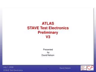
ATLAS STAVE Test Results Version 1. David Nelson July 21, 2008. STAVE TEST SETUP. STAVE. CLOCK. NI Interface. DATA. Stave Buffer. Hybrid 5. Hybrid 2. Hybrid 3. Hybrid 4. Hybrid 1. COMMAND.

E N D
ATLAS STAVE Test ResultsVersion 1 David Nelson July 21, 2008
STAVE TEST SETUP STAVE CLOCK NI Interface DATA Stave Buffer Hybrid 5 Hybrid 2 Hybrid 3 Hybrid 4 Hybrid 1 COMMAND • These tests are to investigate why the hybrids do not accept the “data taking” command as observed by the return data not returning all zeros. • Used pulse generator to drive clock and command on buffer board into U4 • Used 5MHz with 50% duty cycle. • Buffer Board is configured: • With double clock drive, R21 & R22 installed, and back termination, R19, installed. • With Command back termination, R17, removed.
Clock and Command Measurement (1) • Measurements on Stave Hybrid #5 and command termination resistor • Signals have reflections but not serious enough to not recover
Clock and Command Measurement (2) • Measurements on Buffer board U4 • Command has huge reflections and oscillations. Command is not back terminated • The clock also has reflections. Clock is back terminated • The ribbon cables are 50 ohms • The impedance of the interface PWB connecting the ribbon cables to the Stave is unknown at this time.
Clock and Command Measurement (3) • Measurements on Stave Hybrid #1 • Command has reflections and maybe oscillations. Command is not back terminated in Buffer board. • The clock also has reflections. Clock is back terminated • Both signals should be recoverable
Clock and Command Measurement (4) • Measurements on Buffer board U4 with short ribbon cable • Command has reflections and oscillations. Command is not back terminated on Buffer board. • The clock also has reflections. Clock is back terminated • The command problem may be the interface board between the ribbon cable and the Stave
Clock and Command Measurement (5) • Measurements on Hybrid #5 with short ribbon cable • Command has reflections and oscillations. Command is not back terminated on Buffer board. • The clock also has reflections. Clock is back terminated • Both signals should be recoverable.
Conclusions and Observations • A single hybrid appears to work reliably but not the Stave with five hybrids. The commanding and clock are probably functionally OK. • Although the signals are not ideal, There is no reason that the signals should not be recoverable on all of the hybrids 1 through 5. • We noticed that DACG is not tied to the interface board common. • We noticed that the IRET is not connected to the buffer board return. • We tied both DACG & IRET to the buffer board common. We noticed that one of the signals, clock or command is differentiated with one of these tied. We need to investigate more. • There is very likely some other mechanism causing the Stave with 5 hybrids to perform incorrectly. • Possible reasons. • The commanding is NOT the same between running a single hybrid and a Stave with 5 hybrids. Could be something like the actual configurations are a little different. We should try to use EXACTLY the same configurations for both the single hybrid and the Stave with 5 hybrids. • The LVDS clock receiver is not ideally biased to the nominal 1.25 volts center voltage. • The command line has a 1K feedback that are in parallel with the other five or ten hybrids.
Action Items • We need to design a small PWB that has the LVDS receive and drivers, DS90LV019 and associated resistors and capacitors. This will mount piggy-back on the PWB Bryan Holmes is designing. This allows us to probe the received signals. This way we can actually see why the “Data Taking” command is being ignored. • We need to understand the grounding issues with DACG and IRET causing the received command or clock on that AC coupled side being differentiated. It looks like maybe the hybrid power shut down and the signal only saw the protection diodes. • I need to check the impedance of the clock and command pairs on the Stave 07 Port PWB. • My calculation says that the differential impedance 188 ohms and the single ended impedance is 110 ohms. I’ve asked Bryan Holmes to verify this.