Download
1 / 33
360 likes | 519 Views
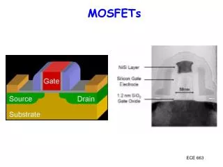
Engineered Substrates for High-Mobility MOSFETs Nathan Cheung Dept of EECS, UC-Berkeley cheung@eecs.berkeley.edu GSR: Eric Liu and Vorrada Loryuenyong. OUTLINE. Motivations for SOI, SSOI, and GeOI substrates Layer Transfer Technologies

E N D
Engineered Substrates for High-Mobility MOSFETs • Nathan Cheung • Dept of EECS, UC-Berkeley • cheung@eecs.berkeley.edu • GSR: Eric Liu and Vorrada Loryuenyong
OUTLINE • Motivations for SOI, SSOI, and GeOI substrates • Layer Transfer Technologies • - Epitaxial Growth and Implantation • - Plasma Activated Bonding • - Delamination • - Post-Delamination Surface Smoothing • FLCC Research • - GeOI layer transfer • - Transfer Thickness Mechanisms • - Thermal-Mechanical Stress Analysis
Strain Si • Ge Various mobility enhancement device structures
Donor wafer Layer Transfer Approaches Splitting By Internal Force H+ H peak Donor wafer SiO2 Handle wafer Wafer bonding Thermal exfoliation > 400°C M.K. Bruel, Electron. Lett. 31, 1201 (1995). Splitting By External Force Mechanically weakened Layer SiO2 Handle wafer Wafer bonding Edge initiated crack propagation En et al, SOI Conference Proc, 163 (1998) Yonehara et al, APL, 64, 2104 (1994)
Direct Wafer Bonding Chemical Cleaning: HF, H2SO4, H2O2 IR Transmission Image Through a Bonded Pair Plasma exposure Room temperature bonding Complete bonding over 4 inch diameter Annealing
Si donor Transferred Si overlayer Handle wafer Delamination Methods (1) Exfoliation of implanted hydrogen [ SOITEC, Amberwave] (2) Cleavage along implant damage region (gas jet) [Sigen] (3) Mechanical rupture of Porous Si (water jet) [Canon]
gcut g (J/m2) gbond gcut> gbond gcut< gbond Temperature (°C) Layer Transfer Theory: Bonding strength > Cutting layer strength Strengths of Bonding and Cutting Layers Separation Modes No transfer Partial transfer Full transfer i = surface energy of interface i Donor Si Donor Si Donor Si SiO2 Receptor Si Receptor Si Receptor Si SiO2 Transferred Si 1 cm gcut > gbondgcut ~gbond gcut<gbond Cho et al, J. Phys. Lett., 92, 5980 (2003) • Full transfer requires a full strength at the bonding interface layer • Non-uniform bonding induces partial transfer
Advantages of Layer Transfer Approach • Donor wafer can be recycled • Transferred thickness and buried oxide thickness • are independently controlled • (100), (110), and (111) Epi layers can be transferred • Multi-stack structures can be achieved with various epi • and transfer combinations
Some state-of-the-art results SOI SSOI GeOI Sigen Canon Amberwave 300mm SOI 50nm Si range=1.2nm SOITEC
Why transfer of Epi Donor Wafers ? • For SOI, Epi Si has less COP defects than bulk Si • For GeOI, no 300mm Ge bulk wafers yet • For s-SOI and SGOI , layer formed epitaxially on SiGe buffer layers
Surface damage 1-2 nm H H H H H H H H O O O O O O O O High coverage of OH Si rich surface High mobility of H2O Defect layer Plasma Activated Bonding PLASMA
3000 O2 plasma 2500 2000 Hydrophilic Si Bonding Energy (mJ/m2) 1500 1000 500 Hydrophobic Si 0 100 400 200 500 600 800 900 700 300 Annealing Temperature (oC) Si/SiO2 Bonding Energy vs. Temperature Si (100) Fracture Strength Cho et al, UCB, 2000.
Requirements for Direct Bonding • Surface micro-roughness ~ nm • No macroscopic wafer warpage • Minimal particle density and size - “soft “ particle size < 0.2 um *Deposited films will need CMP
Surface Smoothing by Hydrogen anneal As-split surface After-anneal surface
Hydrogen Induced Thermal Separation rms ~ 8.5 nm NanoCleave rms ~ 0.8nm Current et al, European Semiconductor, Feb 2000
80 Ultra-Thin SOI Layer Thickness 70 Early 2002 Late 2002 60 10% 50 Range (Max-Min) (Å) 40 Typical Range <25Å 30 20 10 Range Now Independent of Layer Thickness 0 0 100 200 300 400 500 600 700 800 Device Layer Thickness (Å) Ultra-Thin (<1KÅ tSOI) Non-Uniformity
Size: 1x1 cm2 Ge/Si3N4/Si and Ge/SiO2/Si substrates by ion-cut Ge donor wafer Si Substrate Implanted Hydrogen GeOI Ge/Si3N4/Si
Ge/Si3N4/Si surface roughness by AFM (b)GeOI by thermal cut; Tcut=360°C, RMS: 20.5nm (a)GeOI by mechanical cut; Tanneal=205°C, RMS: 17.5nm (Size of AFM images: 5x5µm2; H ion dose: 6x10¹⁶ /cm2.) • GeOI transfer surface roughness > SOI transfer surface • roughness (RMS<7 nm) • Post-transfer smoothing is required
400nm Ge 30nm dry ox Transferred Ge Transferred Ge Si substrate 400 300 200 100 SiO2 SiO2 0 0 100 200 300 400 500 600 700 Thickness,t, (nm) Scan distance (µm) Ge/SiO2/Si by thermal ion-cut • Fabrication processes: • Oxygen plasma activation • for 15sec; • Direct bonding; • Post-bonding annealing: • 130°C for 20h; • 220 °C for 10h; • Thermal-cut at T>270 °C ;
Observed cutting depth SRIM2000 HydrogenDistribution Vacancy Distribution Depth (Ǻ) Ge/SiO2 (or Si3N4)/Si system by ion-cut shows that the cutting depth is deeper than the implantation zone ! Si Ge Ideal crack propagation Pgas Thermal Cut Mixed-mode crack propagation Pgas 1 Data is obtained in courtesy of ZhengXin Liu 2
10 nm 19 nm What controls Transfer Layer thickness ? SOI: H+ 175 keV 5.0 x 1016 cm-2 600C • Ion-cut take place at shallower depth than the center of the hydrogen platelet distribution • The ion-cut location is found to occur at the depth of maximum damage. Ion-cut location 29 nm [100] [011] Höchbauer et al, J. Appl. Phys, 89, 5980 (2001)
Donor Si Donor Si Glass Glass Transfer thickness of Ion-Cut is different with substrate stress Implanted Si (100) H+8 1016 cm-2 28 keV Transferred layer of implanted Si is thicker than non-implanted Si Si (100) Small Area Transfer Large Area Transfer H Peak Implanted Si (100) Thickness Non-implanted Si (100) thickness Si Thickness (m) Transferred Si Transferred Si Top views of transferred layers Distance (m)
300 Implantation at 40 keV 300 H Peak 200 Damage Peak Transferred Thickness (nm) 200 100 100 0 0 1 2 3 4 5 6 0 0 2 4 6 Implantation dose 1016 cm-2 Transfer Thickness versus Implantation Dose Thickness Measurement Data Stress Measurement Data 0 σo -100 SU-8 -200 -300 Si -400 Compressive Stress (Mpa) -500 -600 -700 -800 0 2 4 6 Implantation dose 1016 cm-2 • Transferred thickness is a function of ion implantation dose • Compressive stress induced by implantation was determined by measuring wafer curvature • Compressive stress leads to additional shear forces at the crack tip
Donor Si Donor Si Layer Transfer Without Hydrogen Implantation SiO2 Si (100) Si (111) • Crack tends to propagate into brittle substrate • Crack propagation driving force is inversely proportional to fracture toughness of materials. • Si(100)1: 0.91 MPam1/2 • Si(111)1: 0.82 MPam1/2 • SiO22: 0.7-0.8 MPam1/2 • Non-uniform thermal stress result in non-uniformity of the transferred surface Full Transfer Partial Transfer Transfer Donor Si SiO2 SU-8 Glass Glass Glass Original donor wafer SiO2 on SU-8 SU-8 SU-8 1 cm Transferred Si Top views of transferred layers 1Chen et al., American Ceramic Society Bulletin, 59, 469 (1980) 2Lucas et al., Scripta Metallurgica et Materialia, 32, 743 (1995)
Opening mode, KI Out-of-plane shear mode, KIII KII = 0 KII > 0 KII < 0 Shear mode, KII Layer Transfer – A Mechanical Fracture Perspective • Stress intensity factors • Effect of KII on KI crack propagation loading Desired condition for uniform layer transfer
250 Transferred Thickness (nm) 0 Analytical 0.005 0.020 1/Ecleaved material SU-8/Si (111) SU-8/Si (100) SU-8/SiO2 Transferred Thickness Experimental Data vs. Analytical Data Analytical Model M Film h d P h λh Neutral plane Substrate Substrate λ KII = 0 Σ = Efilm/Esubstrate Ki – Stress intensity factor (mode i) o – Thermal stress I – Moment of inertia of the transferred beam Model by Drory et al, Acta Metall., 36, 2019 (1988)
σo Film h d λh Substrate Derailing Mechanism of Mixed-Mode Crack Propagation Map of Failure Mechanism Mixed-Mode Crack Propagation 1.0 Substrate cracking No cracking Steady state cracking Partial cracking • Interfacial delamination • Partial substrate cracking • Steady state substrate cracking Normalized interfacial toughness, i2/o2h 0.5 Interfacial delamination Stress intensity factor of the kink crack inclined at to the main crack 0 2 1 Normalized substrate toughness, S2/o2h Where kI and kII are the stress intensity factors acting on the main crack and, Thouless et al. (1991)
Thermal Stress Simulation of Ge-SiO2-Si systems by finite element analysis SiO2 Ge Direct Stress σxx (MPa) Annealing T (ºC) y (800 °C) Annealing Ge (100 nm) Ge SiO2 (100 nm) SiO2 x Si (500 μm) Si • Ge layer has a tendency to buckle due to the compressive direct stress. • The interfacial stress may exceed the fracture tensile strength of SiO2 (approximately 110MPa)
y x Ge (50 nm) SiO2 (100 nm) 50 nm Si (500 μm) 300ºC annealing Ge 500ºC annealing 800ºC annealing SiO2 Si Compressive Tensile Thermal Stress Simulation of Patterned Ge-SiO2-Si systems by finite element analysis Max Direct Stress σxx (MPa) 50nm w (nm) 500ºC Direct Stress σxx distribution after annealing
Hole Mobility D D D NMOS (110) (100) S S S (110) Electron Mobility (110) (110) (100) (110) PMOS PMOS D D D (110) (110) (110) (110) S S S (110) (110) (110) (110) (110) (110) Impact of Fin Orientation Source: Professor T-J. King (UCB)
Manufacturing Equipment Issues • High-throughput, low-cost Epi Reactors • CMP or smoothing of SiGe and s-Si • High Current Hydrogen implanters • Plasma Activated Bonders • Mechanical Delamination Machines H+ Plasma Implanter Plasma Bonder Gas Jet Delamination
Summary • Ultra-thin (<10nm) SOI, GeOI, and s-SOI pose new challenges to meet stringent uniformity and roughness specifications • Mechanical stress distribution (bonding-induced and implantation-induced) are key factors in transfer thickness control. • Improved process recipes are needed to ensure thermal stability of sSOI and GeOI structures • Challenges for process control , metrology, and low-cost manufacturability