Download
1 / 37
370 likes | 538 Views
EE40 Final Exam Review Prof. Nathan Cheung. 12/01/2009. Practice with past exams http://hkn.eecs.berkeley.edu/exam/list/?exam_course=EE%2040. Overview of Course. Circuit analysis : Laws: Ohm’s, KVL, KCL Equivalent circuits (series/ parallel, Thevenin, Norton)

E N D
EE40Final Exam ReviewProf. Nathan Cheung 12/01/2009 Practice with past exams http://hkn.eecs.berkeley.edu/exam/list/?exam_course=EE%2040
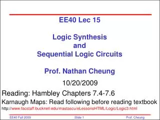
Overview of Course Circuit analysis: Laws: Ohm’s, KVL, KCL Equivalent circuits (series/ parallel, Thevenin, Norton) Superposition for linear circuits Nodal analysis Mesh analysis Phasor I and V Circuit components: R, C, L , sources I-V characteristics energy storage/dissipation First-order transient excitation/analysis: Second Order RLC circuits Bode Plots
Overview of Course Logic gates; Combinatorial logic (sum-of-products, Karnaugh maps), sequential logic etc. Semiconductors Devices pn-diodes (many types) FETs (n-channel, p-channel, CMOS) Useful Diode and FET circuits: Amplifiers: op-amp (negative feedback), rectifiers; wave shaping circuits
Diode Circuit Analysis by Assumed Diode States • 1) Specify Ideal Diode Model or Piecewise-Linear Diode Model • 2) Each diode can be ON or OFF • 3) Circuit containing n diodes will have 2n states • 4) The combination of states that works for ALL diodes (consistent with KVL and KCL) will be the solution ID (A) ID (A) forward bias forward bias reverse bias reverse bias VD (V) VDon
Example Problem: Perfect Rectifier Model Sketch Vout versus Vin Suggested problem: What if there is a 0.6V drop when diodes are on ?
VOUT VIN t t - VC + C + + - - VIN VOUT Diode with Capacitor Circuit (e.g.Level Shifter) VC VIN(min) VOUT (t)= VC(t)+ VIN(t) 1 3 Finds out what happens to VC when VIN changes 1) Diode =open, VC(t)=0, VOUT (t)= VIN(t) 2) Diode =short, VC(t)= -VIN(t) , VOUT(t)=0 3) Diode =open, VC(t)= -VIN(min), VOUT(t)= VIN(t)-VIN(min) 2 ,
Example: Diode with RL Circuit Sketch i(t) Answer Note: i(t) is continuous = L/R = 0.05 msec
200K +- 2V ID D D Non-linear element NLE 1M + - 250K VDS 9mA +- S S Load-Line Analysis We have a circuit containing a two-terminal non-linear element “NLE”, and some linear components. First replace the entire linear part of the circuit by its Thevenin equivalent. Then define I and V at the NLE terminals (typically associated signs) 1V
ID D N L E 200K 200K +- +- 2V 2V S ID ID (mA) D 10 NLE + - The solution ! VDS S VDS (V) 1 2 Example of Load-Line Analysis (con’t) Given the graphical properties of two terminal non-linear circuit (i.e. the graph of a two terminal device) And have this connected to a linear (Thévenin) circuit Whose I-V can also be graphed on the same axes (“load line”) Application of KCL, KVL gives circuit solution
Example : Voltage controlled Attenuator VC and RC Determines rd at Q point of diode
Example : Voltage Controlled Attenuator The large capacitors and DC bias source are effective shorts for the ac signal in small-signal circuits
ID 3-Terminal Device D G VGS = 3 +- VGS = 2 VGS S ID (mA) 10 VGS = 1 VDS (V) 1 2 Three-Terminal Parametric Graphs Concept of 3-Terminal Parametric Graphs: We set a voltage (or current) at one set of terminals (here we will apply a fixed VGS, IG=0) and conceptually draw a box around the device with only two terminals emerging so we can again plot the two-terminal characteristic (here ID versus VDS). But we can do this for a variety of values of VGS with the result that we get a family of curves.
G ID D S 200K +- V +- 2V ID ID VGS = 3 (mA) (mA) 10 VGS = 2 10 The solution ! VGS = 1 VDS VDS (V) 1 2 (V) 1 2 Graphical Solutions for 3-Terminal Devices We can only find a solution for one input (VGS) at a time: First select VGS (e.g. 2V) and draw ID vs VDS for the 3-Terminal device. Now draw ID vs VDS for the 2V - 200KW Thevenin source. The only point on the I vs V plane which obeys KCL and KVL is ID = 5mA at VDS = 1V.
SOLVING MOSFET CIRCUITS: STEPS • Guess the mode of operation for the transistor. (We will learn how to make educated guesses). • Write the ID vs. VDS equation for this guess mode of operation. • Use KVL, KCL, etc. to come up with an equation relating ID and VDS based on the surrounding linear circuit. • Solve these equations for ID and VDS. • Check to see if the values for ID and VDS are possible for the mode you guessed for the transistor. If the values are possible for the mode guessed, stop, problem solved. If the values are impossible, go back to Step 1.
Saturation Triode Cut-off Triode Saturation Cut-off CHECKING THE ANSWERS NMOS • 1) VGS > VT(N) in triode or saturation • VGS ≤ VT(N) in cutoff • 2) VDS < VGS – VT(N) in triode • VDS≥ VGS – VT(N) in saturation 1) VGS< VT(P) in triode or saturation VGS ≥ VT(P) in cutoff 2) VDS> VGS – VT(P) in triode VDS≤VGS – VT(P) in saturation PMOS
Example Problem : MOSFET Circuit Find VGS such that VDS=2V Answer Guess Saturation Mode Check: VDS(=2V) > VGS-VT (=1.5-0.5=1V) MOSFET indeed is in saturation mode
Example Problem : MOSFET Circuit Find small-signal model parameters =10-5 Siemens
How do you guess the right mode ? Often, the key is the value of VGS. (We can often find VGS directly without solving the whole circuit.) ID VGS≤ VT(N) ID VGS= VT(N) + e definitely cutoff probably saturation VDS VDS VGS- VT(N) = e
How do you guess the right mode ? When VGS >> VTH(N), it’s harder to guess the mode. ID triode mode saturation mode VGS - VTH(N) If ID is small, probably triode mode VDS
1.5 kW D ID + VDS _ 4 V G + VGS _ 3 V + _ + _ S EXAMPLE • Since VGS > VTH(N), not in cutoff mode. Guess saturation mode. 2) Write transistor ID vs. VDS: • Write ID vs. VDS equation using KVL: GIVEN: VTH(N) = 1 V, K= 250 m A/V2, l = 0 V-1.
1.5 kW D ID + VDS _ 4 V G + VGS _ 3 V + _ + _ S EXAMPLE • Solve VDS: • ID = 1mA VDS = 2.5 V • Check: • ID and VDS are correct sign, and VDS≥ VGS-VT(N) as required in saturation mode. GIVEN: VTH(N) = 1 V, ½ W/L mnCOX = 250 m A/V2, l = 0 V-1.
1.5 kW D ID + VDS _ 4 V G + VGS _ 3 V + _ + _ S WHAT IF WE GUESSED THE MODE WRONG? • Since VGS > VTH(N), not in cutoff mode. Guess triode mode. 2) Write transistor ID vs. VDS: ID = 2·250·10-6(3 – 1 – VDS/2)VDS • Write ID vs. VDS equation using KVL: GIVEN: VTH(N) = 1 V, K= 250 m A/V2, l = 0 V-1.
1.5 kW D ID + VDS _ 4 V G + VGS _ 3 V + _ + _ S WHAT IF WE GUESSED THE MODE WRONG? • Solve for VDS with quadratic • equation by combining 2) and 3): • VDS = {4 V, 2.67 V} • 5) Check: • VDS > VGS – VT(N) = 2V • Neither value valid in triode mode! • Guess is incorrect. GIVEN: VTH(N) = 1 V, K= 250 m A/V2, l = 0 V-1.
+ _ + _ Another Perspective This circuit acts like a constant current source, as long as the transistor remains in saturation mode. IDSAT does not depend on the attached resistance if saturation is maintained. In this circuit, the transistor delivered a constant current IDSAT to the 1.5 kW resistor. 1.5 kW D ID + VDS _ 4 V G + VGS _ 1.5 kW IDSAT 3 V S
+ _ + _ Another Perspective • The circuit will go out of saturation mode if • VGS < VT(N) or • VDS < VGS – VT(N) • This can happen if VGS is too large or too small, or if the load resistance is too large. IDSAT does depend on VGS; one can adjust the current supplied by adjusting VGS. RL D ID + VDS _ VDD G + VGS _ RL IDSAT VGS S
+ _ ANOTHER EXAMPLE • What is VGS? • No current goes into/out gate. • VGS = 3 V by voltage division. • Guess saturation (randomly). 1.5 kW 2 kW D ID 4 V G 2) Write transistor ID vs. VDS: + VDS _ + VGS _ 6 kW • Write ID vs. VDS equation using KVL: S GIVEN: VTH(N) = 1 V, K= 250 m A/V2, l = 0 V-1. VDS=2.75V consisitent with saturation mode Effectively the same circuit as previous example: only 1 voltage source in this case
The CMOS Inverter: Current Flow i I N: sat P: sat VOUT N: off P: Triode C V DD VDD S G N: sat P: Triode D VIN VOUT B D E A D G N: Triode P: sat S N: Triode P: off 0 VIN VDD 0
Another CMOS Example: The LATCH CLK CLK VDD Data (VIN) is written to the internal node (VOUT_INT) when the clock is low. VOUT remains frozen. When the clock is high. The (inverted) internal node voltage is written to VOUT. The internal node VOUT_INT remains frozen VDD CLK VOUT_INT VOUT VIN CLK
CLK CLK THE LATCH When CLK is low the left-hand transistors conduct. The right-hand transistors are open. VOUT_INT is charged to VIN. VDD VDD CLK 0 V VDD VOUT_INT VOUT VIN VOUT remains the same; there is no charging path. CLK VDD 0 V
CLK CLK THE LATCH When CLK is high, the right-hand transistors conduct. the left-hand transistors are open. VDD VDD CLK VDD 0 V VOUT_INT VOUT VIN VOUT is changed to VOUT_INT. CLK VOUT_INT remains the same; there is no charging path. VDD 0 V
CLK CLK CONCEPT OF STATE VDD A latch stores a “1” or “0”. The stored value is known as the “state”. VDD CLK Next State Current State This is one of the basic elements needed to make a “state machine” (covered in EE 20 and CS 61C). VIN CLK
LATCH AS GATEKEEPER A signal may have to go through a complex system of gates, with paths of different delays: possibility of false output! Sequential Element Prevents changes in output until signaled Combinatorial Logic Signal propagates all the way through Includes our logic gates: NAND, NOT, etc.
Amplifier Efficiency Source Pi = (10-3V)2/105 =10-11 W Power Supply A Load Source Amplifier Load P0 = (8V)2/8 =8W Power Supplies Ps = 15W+7.5W = 22.5W Power Supply B Amplifier Pd = 22.5W+10-11W-8W = 14.5W Amplifier Efficiency = 8/22.5 =36%
Differential Signal and Common Mode Signal Redefine the inputs in terms of two other voltages: 1. differential mode inputvidvi1– vi2 2. common mode inputvicm (vi1+ vi2)/2 so that vi1 = vicm + (vid/2) and vi2 = vicm - (vid/2) “differential mode gain” “common mode gain”
Common Mode Rejection Ratio • Example • Differential signal from sensor = 1mV (peak). • We want outputs signal > 1V implies Ad> 1000 • Common mode signal =100V (from power line). • We want common mode signal < 0.1V implies • Acm <10-4 • Therefore CMRR needs to be > 20log(107)= 140dB
Offset Voltage, Offset Current, and Bias Current Given Voff=2mV IB= 100nA Ioff= 20nA Acm=1 Ad=100 Both input terminals to ground through 100k resistors Use superposition Vo = Ad(Vvoff+VIoff)+ Acmvicm= 100(0.001667+0.001667)+1(0.01)=0.3343V