Download
1 / 13
130 likes | 133 Views
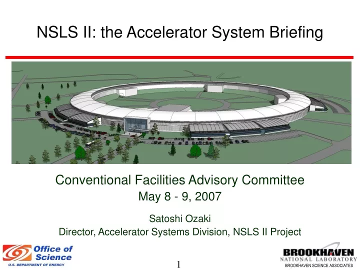
NSLS II: the Accelerator System Briefing. Conventional Facilities Advisory Committee May 8 - 9, 2007 Satoshi Ozaki Director, Accelerator Systems Division, NSLS II Project. Outline. Overview of the accelerator system Injection system design Storage ring lattice

E N D
NSLS II: the Accelerator System Briefing Conventional Facilities Advisory Committee May 8 - 9, 2007 Satoshi Ozaki Director, Accelerator Systems Division, NSLS II Project
Outline • Overview of the accelerator system • Injection system design • Storage ring lattice • Establishing the accelerator footprint (5/2/07 meeting • Consideration for the future upgrade • Beam Stability Taskforce activities (Sam Krinsky) • Steps toward the “requirement” document for accelerator systems and implementation of the configuration control
NSLS-II Concept NSLS-II Machine Concept • New Electron Storage Ring • Medium Energy (3 GeV) • Large Circumference (791.5 m) • Large Current (500 mA) • Superconducting RF • Top-Off Operation • DBA30 Lattice • Ultra-Low Emittance (<1 nm) • Damping Wigglers (21 – 56 m) • Large Dipole Bend Radius (25 m) • Provision for IR Source • Three-pole wiggler x-ray sources Selected Technical Challenges • Lattice Design: dynamic aperture, energy acceptance • Source Stability: vibrations, thermal issues, feedback • Impedance Budget: Small gap (5 mm) ID tapers, etc • Insertion Device: CPMUs, EPUs, SCUs(?)
Injection System Configuration • Pre Injector: 200 MeV S-band Linac operating at 3 GHz • Linac tunnel + Klystron gallery • Linac-to booster beam transfer line with two critical devices • Space in the linac tunnel and booster tunnel to install the transfer line, and partition wall with a beam port between them • Booster synchrotron: 3 GeV (upgrade to 3.6 GeV) • ~158m in circumference • 10 n Coulomb per cycle • ~1 cycle per minute for top-off operation: • ~1 Hz (Interruptible if needed) for test and tuning operation: • Separate booster tunnel and RF power & service building • Booster to storage ring beam transfer line with two critical devices
Storage Ring Configuration • Storage Ring: • ~791.5 m in circumference • Double bend achromatic lattice with 15 long straights (~8m) and 15 short straights (~6m) • Long straights for beam injection, RF, Damping Wigglers, and other insertion devices • Short straights for narrow gap undulators for high brightness beams • Area above the tunnel for power supplies, instrumentation electronics, and other service equipment • Space for 3-Pole Wigglers just upstream of the second dipole (active length ≤0.4m).
CAD Picture of Storage Ring Configuration Beam shutter Insertion device installed Front end Insertion device being transported Tunnel wall thickness varies depending on the distance to the center of the stored beam
Storage Ring Functionalities • 3 GeV, 500 mA 1% • Upgradeable to 3.6 GeV or 700 mA • Estimated beam life-time: 2 – 3 hours • Top-off injection to achieve better than 1% beam current variation for the heat load stability • Ultra-small emittance (x, y) : • Bare Lattice: ~2 nmrad Horizontal & ~0.01 nmrad vertical • Baseline: ~1 nmrad horizontal & ~0.008 nmrad vertical • Fully built-out: ~1/2nmrad horizontal, ~0.008 nmrad vertical • High level of reliability and stability of operation • Magnet Inventory: • 60 dipoles: 2.5 m long, 54 with 35 mm gap, 6 with 93 mm gap • 330 quadrupole magnets: • 390 sextupole magnets: • 210 or more corrector magnets
Accelerator Footprint Development Status • Injection Linac: • Tunnel enclosure for a 200 MeV S-band linac as was for the CDR, • klystron gallery can be either above or on a side of the linac tunnel • Booster: • Circumference ~158.3 m with 4 straights (~7 m long each) • Almost ready to fix the straight length • The entire injection system complex will be moved clockwise by one super-period, and the location and orientation of the booster and linac will be optimize. • Design of beam transfer lines are to be finalized according to the placement of the linac and booster • Storage ring lattice: • The circumference of the ring will be increased to 791.5 m in order to rationalize the harmonic number of the ring • With due consideration of ID and vacuum equipment requirement, we will maintain the short straight length at 6.6 m • The long straight will be about 8.5 m long, the detailed length depending on the actual length of sectors • The super-long straights will be treated as a stretch goal, and when a need is identified and satisfactory lattice is confirmed, the straights will be implemented within the baseline tunnel design. • In order to maintain this implementation feasible, the inner wall of the tunnel will be modified at three super-periods to allow more space.
Provisions for Future Upgrade Super-long straight For the in-tunnel lengthening of the straight, the inside wall of the SR tunnel must be recessed from a straight line over one super-period Upgrade by ERL A superconducting linac must be built outside the SR ring with a tunnel under the SR building for injection and return line. Compared to this complexity, performance gain is rather the minimal. Therefore, this is not a very serious possibility.
Beam Stability Requirement • The beam stability required: 10% or less of the beam size (~3m) • Beam Stability Workshop: April 18-20, 2007: Sam Krinsky • Settling and vibration (natural and self-inflicting) of the accelerator tunnel and experimental hall floor/beamlines • Temperature stability • Mechanical engineering consideration • Magnet power supply and RF noise issue • Closed orbit correction with slow and fast feedback • External Participants • Extensive experience and lessons learned: M. Boege (SLS/PSI) J. Byrd (ALS/LBL) J. Chen (Taiwan) Y. Dabin (ESRF) R. Hettel (SSRL/SLAC) Chair J. Jacob (ESRF) J. Maser (APS/ANL) R. Mueller (BESSY) D. Shu (APS/ANL) J. Sidarous (APS/ANL) O. Singh (APS/ANL) C. Steier (ALS/LBL)