Download
1 / 25
250 likes | 258 Views
5 th Roma International Conference on Astroparticle Physics. Data acquisition system for the Baikal-GVD neutrino telescope. Vladimir Aynutdinov for Baiakal collaboration S eptember 30, 2014. OUTLINE. 1. Baikal site 2. GVD design and electronics 3. Engineering array 2014 4. Summary.

E N D
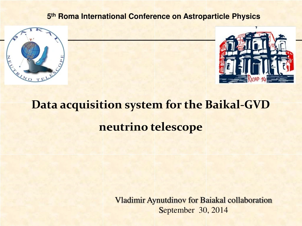
5th Roma International Conference on Astroparticle Physics Data acquisition system for the Baikal-GVD neutrino telescope Vladimir Aynutdinov for Baiakal collaboration September 30, 2014
OUTLINE 1. Baikal site 2. GVDdesign and electronics 3. Engineering array 2014 4. Summary
Collaboration 7 Institutions, ~ 50 authors • State Marine U. Petersburg • JINR Dubna INR, MSU Moscow • Techn State U. Nizhni Novgorod Germany: EvoLogics GmbH • Irkutsk State University
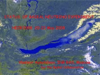
Scattering cross section, m-1 Absorption cross section, m-1 Baikal Baikal , nm , nm The BAIKAL Site Lake Baikal, Siberia Baikal water properties: Abs.Length: 22 ± 2 m Scatt.Length: 30-50 m 1370 m maximum depth. • Distance to shore ~4 km • No high luminosity bursts from biology. • No K40 background. • Deployment simplicity: ice is a natural deployment platform Summer expedition Winter expedition Day temperature Baikalsk 4
Gigaton Volume Detector GVD 2015 – 1 Cluster with 8 strings (196 OM) 2020 –12 Cluster (1st GVD phase - 0.4 km³) ) The pressure-resistant optical sensors register flashes of the Cherenkov light emitted by charged particles from collisions of high-energy neutrinos. Cluster – 8 str. Optical sensors Cherenkov light Muon Cascade Neutrino R = 60 m H = 350 m Optical module. GVD String 24 OM
GVD Optical module Quantum efficiency R7081-100 Hamamatsu D=10 inch. SBA photocathodeQE ≈ 35% @ 400nm; Gain ~107, dark count ~8 kHz Angular sensitivity Φ220mm OM electronics Mu-metal cage PMT Optical gel Glass pressure-resistant sphere VETROVEX(17”)
Optical module electronics HV converter: SHV 12-2.0 K 1000 P 0 …+ 2000 VDC, stability 0.05% ripple and noise 8 mVpk-pk Passive divider: 18 M 2-channel amplifier: Output channel and PMT noise monitoring channel. LED flasher: 2 LEDs L7113: 470 nm, ~6 ns - Intensities regulation: 1…~108 photons - Flashes delay regulation: 0 … 1000 ns Slow control board: SiLabs C8051F121 Control of electronics operation and monitoring of PMT parameters via RS485 interface. Power consumption – max 0.3A12V
ADC electronics FPGA FADC (AD9430) 12bit, 200 MSPS FPGA (Xilinx Spartan 6) • Trigger channel: 2-level digital comparator forms low threshold L and high threshold H channel requests ( GVD basic trigger: L&H coincidence of neighboring channels). • Data channel (triggered) consists of double-buffered memory and data transmitter. - Monitor channel (non-triggered) includes peak detector and amplitude analyzer. Functional scheme of one FADC channel Data channel Monitor channel LED pulse Single PE pulses Noise Monitor histogram examples Waveform stamp example (5 mks) 8
Measuringchannel PMT: 107 90 m coax.cable <Ape> = 30 ch Ape ~ 10% Amplifier: 14 FADC: ± 2V • PMT: nominal gain: 1107; Amplifier: kamp=14; Cable: ~0.7: 108 in total • Pulse width after cable: ~20 ns FWHM. • FADC: 4V. 12 bit, 5 ns time bin. • Linearity range: 1 ─ 102 p.e.; • Count rate (0.3 PE) ~ 25 kHz in average. • Threshold (min): ~ 0.20×Ape 1 2 N 11 <f> = 23 kHz 12 GVD Section: 12 channels Count rate distribution for all channels (2014), kHz. Distribution of the channels on Ape(2014), ADC chan.
GVD Section Section (basic DAQ cell) – 12 OM and Section electronics module (SeM). 12-channel ADC unit: PMTs analog pulse conversion, time synchronization, data processing, local trigger. Data transmission: Two outputs of ADC board: optical output (for future detector extension) and 100 BASE-TX (present stage). shDSL modem: Extending the Ethernet line up to 1 km. Slow control board: OM power on/off and control of OM operation (RS485). MOXA IEX-402-SHDSL SeM MASTER SLOW CONTROL FADC
Engineering array 2014 The current stage of Baikal-GVD Cluster comprising 5 strings (112 OM) • 14 April – 25 September: 169 days • Data taking: 122 days • Efficiency: 72.2% • Total: 452 Runs • Data : 1.26 108 events Basic trigger: coincidences of neighboring OM with low and high thresholds (1 & 3 p.e.)
Background condition Channel count rate for two strings: April – September 2014 String 3, Section 2 (Up) String 3, Section 1 (Down) String 5, Section 1 (Down) String 5, Section 2 (Up) N • 1. Significant count rate variations depending the season (chemiluminescence). • 2. Strong correlation between peak of activity. • 3. Average count rate ~20-25 kHz (0.3 p.e.) <f> = 23 kHz Count rates f for all channels, from April to August 2014 f, kHz
Stability of the channels • Selected parameters: • PMT high voltage (HV) • Channel gain (G ) • Noise rejection factor ( ): count rate ratio for thresholds 2 p.e / 0.5 p.e. SPEspectrum measured with LED (black) and PMT noise (red) N N Run 299 <G> = 1.17108 G ~ 10% N channels Channel distribution on max. HV deviation N channels HV max deviation: 0.5V … 1.2V (~0.05% stability) May – September 2014; HV: 1100V … 1800V: PMT Gain 107 N channels 1.3 1.6 1.9 1.0 0.7 G108 Channel distribution on the Gain 1100 V 1800 V 1.3 V 0.5 V
LED flashes detection Ch 64 ~1 p.e. RUN C0247. t, ns 3.6 p.e. Ch 63 LEDs L7113: 470 nm, FWHM: 6 ns Ch 62 Light propagation distance for maximum LED intensity ~100 m along the string in Baikal water. 12 p.e. 36 p.e. Ch 61 Ch 60 107 p.e. • Experimental time consistent with expectation for the Q up to 2102 p.e. within ~3 ns accuracy. • Possibilities of time walk effect direct estimation Reference channel 257 p.e. 15 m Ch 59 528 p.e. “On the Velocity of light signal …” NIM A482 (2002), 304-306 Ch 58 LED 578 p.e. Ch 57 R, m
Atmospheric muon detection Trigger Coincidence of neighboring OM Statistics 14 Apr – 25 Sep: 1.17× 10⁸ events Selection – Q > 2 p.e. Time calibration: LED Data consistent with expectation dt distribution between neighboring channels
Summary 1. Results obtained on GVD engineering array demonstrate reliable, stable and correctness operation basic elements of the telescope. 2. Baikal -GVD technical design is basically finalized. 3. The nearest plans (April 2015): full scale GVD cluster in Baikal lake (8 strings).
( ) ) ( ( ) ( ) A, mV Increasing allowed trigger rate: 5-10Hz -> 50Hz Trigger rate is limited by the data transmission rate from the strings to DAQ-center: 5-6 Mbit (Ethernet, shDSL modem, 1 km line length). New firmware of the Master board: on-line data filtering. Cut the pulses from data frame and paste to output data stream. Rejection factor : 30-40 Time, 5 ns
Power supply 300 VDC power supply system. Power commutator 300 VDC (12 channels) was specially designed for Baikal at 2011 Three-level power supply system: 1-st. Cluster center level (300V). Switching on/off string power supply. 2-nd. String level (300V). Switching on/off section power (independently ADC and OM). 3-rd. Section level (12V). Switching on/off OM power. String power consumption: 0.45A300V => Cluster (8 strings) ~1.2 KW
ADC board 12-ch 200 MSPS ADC FADC (AD9430) 12bit, 200 MSPS FPGA (Xilinx Spartan 6) • Trigger logic: 2-level adjustable digital comparator forms low threshold L and high threshold H channel requests - Data channel (triggered) consists of double-buffered memory and data transmitter. - Monitor channel (non-triggered) includes peak detector and amplitude analyzer. - Trigger logic(L&H coincidence of neighboring channels - Data readout from ADC buffer - Control of OM mode of operation - Connection via local Ethernet to the cluster DAQ center
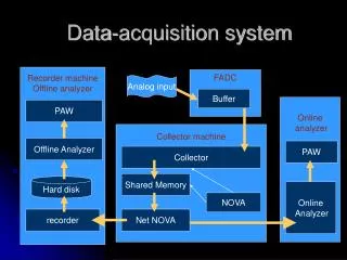
GVD cluster architecture Cluster DAQ center Basic principles of GVD design: • Simplicity of all elements; • Deployment convenience from the ice cover; • Detector extendability and configuration flexibility String electronic module SECTION Basic GVD elements • Optical module (OM); • Section: 12 OM (spaced by 15m) & Section electronic module (12 FADCs) • String: 2 Sections & String electronic module • Cluster: 8 strings & DAQ center. STRING SECTION Section electronic module Cluster with 8 two-section strings (2015) Optical module
Triggering and Data Transmission SECTION CLUSTER
Operational statistics • 14 April – 25 September: 169 days • Data taking: 122 days • Efficiency: 72.2% • Total: 452 Runs • Data : 1.26 108 events • Monitoring: 803799 records Master data over 2014 Time between events