Download
1 / 28
280 likes | 444 Views
Baikal Neutrino Experiment. Vladimir Aynutdinov for the Baikal Collaboration Athens, October 13, 2009. Collaboration. Institute for Nuclear Research, Moscow, Russia. Irkutsk State University, Russia. Skobeltsyn Institute of Nuclear Physics MSU, Moscow, Russia.

E N D
Baikal Neutrino Experiment Vladimir Aynutdinov for the Baikal Collaboration Athens, October 13, 2009
Collaboration Institute for Nuclear Research, Moscow, Russia. Irkutsk State University, Russia. Skobeltsyn Institute of Nuclear Physics MSU, Moscow, Russia. DESY-Zeuthen, Zeuthen, Germany. Joint Institute for Nuclear Research, Dubna, Russia. Nizhny Novgorod State Technical University, Russia. St.Petersburg State Marine University, Russia. Kurchatov Institute, Moscow, Russia.
Introduction Neutrino telescope NT200 (NT200+) Design Selected Physics Results Future Gigaton-Volume Detector GVD in Baikal lake Preliminary Design Prototype string for BAIKAL-GVD detector (2009) Summary OUTLINE
Baikal - Milestones Since 1980 Site tests and early R&D started 1990Technical Design ReportNT200 1993 NT36 started: - the first underwater array - the first neutrino events. 1998 NT200 commissioned: start full physics program. 2005NT200+ commissioned (NT200 & 3 outer strings). 2006 Start R&D for Gigaton Volume Detector (GVD) 2008 In-situ test GVD electronics: 6 new technology optical modules 2009 Prototype string for GVD: 12 optical modules 2011GVD cluster (3 strings), Technical Design Report
Absorption cross section, m-1 Scattering cross section, m-1 Baikal Baikal , nm , nm BAIKAL Water Optical Properties Scat.Length: 30-50 m <cosθ>: 0.85-0.90 Abs.Length: 22 ± 2 m No high luminosity bursts from biology
Ice as a natural deployment platform cable Shore cable mounting Winches used for deployment Deployment with winches tractor with ice cutter ice slot cable layer
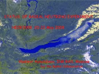
Status of NT200+ NT200+ is operating now in Baikal lake Quasar photodetector (=37cm) LAKE BAIKAL NT200: 8 strings (192 optical modules ) Height x = 70m x 40m, Vinst=105m3 Effective area: 1 TeV~2000m² Eff. shower volume: 10 TeV~ 0.2 Mton ~ 3.6 km to shore, 1070 m depth NT200+ = NT200 + 3 outer stringw (36 optical modules) Height x = 210m x 200m, Vinst = 4106m3 Eff. shower volume: 104 TeV ~ 10 Mton
Selected Physics Results NT200 Magnetic Monopoles Atmospheric muon background Atmosphericneutrinos WIMP from the Sun WIMP from the Earth Center Diffuseneutrinoflux Neutrinosfrom GRB
High energy neutrino: searching for diffuse neutrinos based on cascades reconstruction New analysisofexistingdatawithvertex, energyanddirectionreconstructionof cascades: improvementofpublishedlimitby a factorof ~ 3 Cascade reconstruction: dlgE ~ 10%; dr ~ (5-10)%; d ~ 5o New cut: Nhit >18 (E >100 TeV) Old cut (Nhit >48) The 90% C.L. “all flavour ” limit, e:: = 1 1 1 Cut E>10 TeV for up-going cascades Cut E>100 TeV for down-going cascades E2 Фn< 2.9 ·10-7GeV cm-2 s-1 sr-1 (Cascades Baikal, 2008) E2 Фn< 2.2 ·10-7GeVcm-2s-1sr-1 (Muons AMANDA-II, 2007) Hit channel multiplicity Energy distribution of experimental (red), generated (blue) and reconstructed (black) events from atmospheric muons.
WIMP Neutrinos from the Sun Preliminary • Neutralino (WIMP) asfavored Dark Matter candidate • - Gravitationallytrapped in the Sun (or Earth) • theSun wouldbe a neutrino-source (annihilation) “Indirect“ WIMP searches Baikal NT200: 1998-02, hard Preliminary AMANDA-II’2001, hard Baksan’1997 MACRO’1998 Super-K’2001 IceCube-22’2007, hard Sun-mismatch angle Ψ (Muon/Sun): data and background (histogram) No excess of events above atm. BG Flux Limits
Search for fast monopoles 90% C.L. upper limit on the flux of fast monopole For a Dirac charge g = 68.5 e, Cerenkov radiation emitted by monopoles is 8300 times more that of a muon. Event selection criteria: 1.Hit channel multiplicity : >30 pairs of PMTs hit. 2. Upward moving light patterns: time-vertical-coordinate correlation. Background - atmospheric muons. No excess over the expected background was found. Amanda II (preliminary) Limit on a flux of relativistic magnetic monopoles (1003 days of live time): F < 4.6 10-17 cm-2 sec-1 sr-1
Search for neutrinos from Gamma-Ray Bursts Analysis of time and directional correlations between NT200 events and GRB F(Ev)=N90 / Seff(Ev) Experimental data NT200 data from April 1998 to May 2000 GRB data: - basic BATSE catalog (triggered bursts): 155 - non-triggered GRB: 148 Signal search: Time window: T90 +10 s Half angle of observation cone: Ψ = 5o Background: Time interval (tGRB + 1000 s) -(tGRB – 1000 s) (excluding signal window); =10. 90% C.L. upper limits on the GRB neutrino fluence Green's function for NT200, Super-Kamiokande and AMANDA For Waxman – Bahcall spectrum and triggered GRB E2 1.1×10⁻⁶ GeVcm-2 s-1 sr-1, E>100 TeV. 90 - event upper limit N90 - 90% C.L. upper limit on the number of events per GRB
Gigaton Volume Detector (GVD) in Lake Baikal R&D status
Optimisation of GVD configuration (preliminary) Parameters for optimization: Z – vertical distance between OM R – distance between string and cluster centre H – distance between cluster centres Trigger:coincidences of any neighbouring OM on string (thresholds 0.5&3p.e.) PMT:R7081HQE,10”, QE~0.35 The compromise between cascade detection volume and muon effective area: H=300 m R = 60 m Z = 15 m R=60 m R=80 m R=100 m Cascade detection volume Muon effective area
Preliminary design 12 clusters of strings NT1000: top view Layout: ~2300 Optical Modules at 96 Strings String: 24 OM 2 Sections with 12 OM Strings are combined in Clusters 8 strings Cascades(E>100 TeV): Veff ~0.3–0.8 km3 δ(lgE) ~0.1, δθmed~ 2o- 4o Muons (E>10 TeV): Seff ~ 0.2 – 0.5 km2 δθmed~ 0.5o-1o L~ 350 m String section, 12 OM 15 m R ~ 60 m Cluster of strings
Cluster of strings 8 Strings String – 2 sections (2×12 OM) Cluster DAQ Centre: - PC-module with optical Ethernet communication to shore (data transmition and claster synchronization) - Trigger module with 8 FADC channel for the measure of string trigger time; - Data communication module – 8 DSL-modems, modem data flaw up to 7 Mbit/s for 1 km. - Power control system Calibration system Two Lasers Cluster DAQ center Synchronization – common signal “Acknowledge” for all strings.
String Section – basic cell of the Cluster • Section consist of: • - 12 Optical Modules • - BEG with 12 FADC channels • Service Module (SM) with LEDs for OM calibration, string power • supply, and acoustic positioning system. • Trigger:coincidences of neighbouring OM (threch. ~0.5&3 p.e.) • expected count rate ~ 100 Hz • Communication: DSL-modem: expected dataflow ~0.5Mbit/s • (only time intervals containing PMT pulses are transmitted)
OM Measuring channels PMT12 PMT1 BEG 90 m coax. cable 90 m coax.cable Amplifier FADC 12 Amplifier FADC 1 … The new generation Baikal Optical module PM: XP1807(12”), R8055(13”), R7081HQE(10”) QE ~0.24 QE ~0.2 QE~0.35 HV unit: SHV12-2.0K,TracoPower OM controller: monitoring, calibration, and PMT control; Amplifier: Kamp = 10 BEG (FADC Unit): - 3 FADC-board: 4-channel, 12 bit, 200 MHz; - OM power controller ; - VME controller: trigger logic, data readout from FADC, and connection via local Ethernet Kdin~107
GVD project – experimental studies • NT200+ array is a first step toward GVD • (2006...2007) • NT200+ has approximately same scale as a cluster of GVD and has allowed to verify detector response simulation, and systems of communication and synchronization. • GVD optimization: on the basis of simulation program tested with NT200+; • New communication system: underwater Ethernet and DSL-modems was tested with NT200+. • String time synchronization: NT200+ laser light source. 10m NT200+ In-situ tests of basic elements of GVD measuring system with prototypes strings (2008...2009) Investigation and tests of new optical modules, DAQ system, cabling system, triggering approaches. Prototype string 2009
X3 100m 100m 100m X1 X2 NT200+ time sinchronization with Laser Laser intensity : cascade energy (1012 – 5 1013 ) : (10 – 500) PeV NT200+ laser light source allows to test the time synchronization between the channels of the strings of GVD cluster Deviation of time differences between NT200+ channels measured with laser from expected value in dependence on distances between channels. Time synchronization accuracy 3…4 ns up to distances ~150 m Laser
GVD prototype string 2008: Prototype of one String Section with 6 new technology OM; 2009: Prototype of the String with two Sections: 12 OM, 2 BEGs with FADC, PC Module, Service Module BEG SM BEG PC NT200+ with experimental string String communication center Optical module
Basic parameters of prototipestring String length: 110 m Number of Optical Modules: 12 Number of Sections: 2 Number of FADC channels: 12 PMT: Photonis XP1807 (12”) : 6 Hamamatsu R8055(13”) : 6 FADC Time Window: 5 mks FADC frequency: 200 MHz • Data analysis in progress now • Monitoring of the optical module operation. • Test the string operation with LED and LASER. • Experimental material: April – Jun 2009
Monitoring of Optical Module operation • OM monitoring parameters: • PMT high voltage; • PMT count rate; • Temperature; • OM low voltages: 12 V, 5 V, -5 V … Example of PMT count rate monitoring OM3 OM5 OM temperature Example of PMT voltage monitoring PMT voltage :
Time resolution of measuring channels (in-situ tests) LED flasher produces pairs of delayed pulses. Light pulses are transmitted to each optical module (channel) via individual optical fibers. Delay values are calculated from the FADC data. Measured delay dT between two LED pulses LED2 LED1 dT (Expected)=497.5 ns <dT (Experiment) > = 498.3 ns <(dT) >= 1.6 ns Example of a two-pulse LED flasher event (channel #5) LED1 and LED 2 pulse amplitude
Time accuracy of measuring channels In-situ test with Laser Time accuracy T (time resolution) & (accuracy of time calibration with LED flasher) Test with LASER T = <dTLASER – dTEXPECTED> dTEXPECTED = (r2-r1)cwater dTLASER - time difference between two channels measured for Laser pulses (averaged on all channel combinations with fixed (r2-r1)) OM#1 OM#2 OM#3 Differences between dT measured with Laser and expected dT in dependence on distances between channels dr OM#4 OM#5 OM#6 110 m OM#7 T < 3 ns OM#8 OM#9 r1 OM#10 OM#11 OM#12 r2 LASER 97m T distribution on channel combination
CONCLUSION 1. BAIKAL lake experiment is successfully running since 1993 - The First Underwater Array - First Neutrino Candidates 2. NEW configuration NT200+ starts work at April 2005 -Improved cascade reconstruction, increased effective volume for cascades; - NT200+ gives good possibilities to optimise the design and to investigate the key elements of future GVD detector. 3. Start R&D for Gigaton Volume (km3-scale) Detector GVD - A “new technology” prototype string was installed: 12 OMs with 12”/13” PMT - In-situ tests of the prototype string with underwater laser and LED flasher shows good performance of all string elements. - GVD Technical Design Report is expected at 2011
Low energy muon neutrinos Lake Baikal (NT200) & South Pole (Amanda) CompleteskycoverageincludingcentralpartsofGalaxy Skyplotof NT200 neutrinoevents (galacticcoordinates) ETHR 15-20 GeV 372 Neutrinos in 1038 Days (1998-2003) 385 events from Monte-Carlo (atmospheric neutrino) Lake Baikal South Pole