Download
1 / 51
610 likes | 985 Views
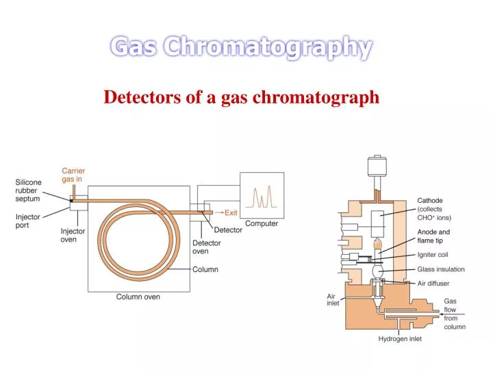
Detectors of a gas chromatograph. The Ideal Detector Adequate sensitivity - range 10 – 18 to 10 – 15 g analyte/s Good stability and reproducibility A linear response to analyte that extends over several orders of magnitude A temperature range from room temperature to at least 400 o C

E N D
The Ideal Detector Adequate sensitivity - range 10–18 to 10–15 g analyte/s Good stability and reproducibility A linear response to analyte that extends over several orders of magnitude A temperature range from room temperature to at least 400o C A short response time that is independent of flow rate High reliability and ease of use Similarity in response toward all analytes of alternatively a higher Predictable and selective response toward + classes of analytes Nondestructive of sample http://www.people.virginia.edu/~roa2s/chem_551/8/tsld002.htm
Detector Requirements • High Sensitivity: • Sensitivity refers to the change in detector response as a function of the change in the amount or concentration of the analyte. • S = dR / dC • or S = dR / dQ • where S is sensitivity, R is detector response, C is concentration of the analyte in the detector, and Q is the total quantity of the analyte in the detector. • Detector sensitivity is best measured as the slope of the calibration graph, a plot of detector response vs. analyte concentration or quantity.
The range over which the detector sensitivity is constant is called the linear dynamic range, and the entire range over which response varies with concentration or quantity is called the dynamic range of the detector. The lower limit of detection is a function not only of the detector sensitivity but of detector noise. Detector noise is defined as the standard deviation of the detector response when no sample is present and is referred to as the root-mean-square noise (Nrms). The detection limit (DL) is defined as the quantity or concentration required to produce a response which is three times the detector noise). DL = 3 Nrms / S H.H. Hill and D.G. McMinn (Ed.), Detectors for Capillary Chromatography, Wiley, 1992. pp 2-3.
2) High Selectivity The selectivity of a given compound over a potentially interfering compound can be measured by the ratio of the detector sensitivities. Selectivity (SEL) is reported in terms of relative molar response or as relative weight response. SEL = S1 / S2 Where S1 is the detector sensitivity of the compound of interest and S2 is the detector sensitivity of the potentially interfering compound. When selectivity is greater than three orders of magnitude for most potentially interfering compounds, it is sometimes referred to as specificity and the detector is said to be specific for that compound or class of the compounds.
Detector types are: 1)FID ( flame ionization detector ) 2) TCD ( thermal conductivity detector ) 3) ECD ( electron capture detector )4) FPD ( flame photometric detector ) 5) HID ( helium ionization detector )6) NPD ( nitrogen-phosphorus detector )7) PID ( photo ionization detector )8) TID ( thermionic ionization detector )9) CCD ( catalytic combustion detector ) 10) NPD/DELCD ( combination NPD and dry electrolytic conductivity detector ) 11) FID/DELCD ( combination FID and dry electrolytic conductivity detector )12) FID/FPD ( combination FID and FPD )13) Dual FPD ( dual wavelength FPD for both sulfur and phosphorus )14) FID dual FPD ( dual FPD plus FID combination )
Thermal Conductivity Detector (TCD) Introduction A TCD detector consists of an electrically-heated wire or thermistor. The temperature of the sensing element depends on the thermal conductivity of the gas flowing around it. Changes in thermal conductivity, such as when organic molecules displace some of the carrier gas, cause a temperature rise in the element which is sensed as a change in resistance. The TCD is not as sensitive as other detectors but it is non-specific and non-destructive. Instrumentation Two pairs of TCDs are used in gas chromatographs. One pair is placed in the column effluent to detect the separated components as they leave the column, and another pair is placed before the injector or in a separate reference column. The resistances of the two sets of pairs are then arranged in a bridge circuit. The bridge circuit allows amplification of resistance changes due to analytes passing over the sample thermoconductors and does not amplify changes in resistance that both sets of detectors produce due to flow rate fluctuations, etc.
Schematic of a bridge circuit for TCD detection Two filament in one cell ( reference side ) --- carrier gas only The other cell ( sample side ) --- carrier plus sample flowing 1. Universal 2. Used primarily for gas analysis 3. Sensitive few ppm
Flame Ionization Detector Introduction The flame ionization detector (FID) is the most sensitive gas chromatographic detector for hydrocarbons such as butane or hexane. With a linear range for 6 or 7 orders of magnitude (106 to 107) and limits of detection in the low picogram or femtogram range, the FID is the gas chromatographic detector for volatile hydrocarbons and many carbon containing compounds. FID Responds to all organic compounds except for formic acid. Response greatest with hydrocarbons and decreases with substitution. Except for vapor of elements in Groups I and II, does not respond to inorganic compounds. Sensitivity high due to low noise level. Insensitivity to water, the permanent gases, and inorganic compounds simplifies the resolution of components in analysis of aqueous extracts and in air pollution studies.
Flame Ionization Detector Consists of a stainless steel burner assembly installed in the detector compartment and a electrometer system in a separate unit adjacent to the gas chromatograph Often it is installed in the tandem with the thermal conductivity cell Effluent form the column enters burner base through millipore filters which remove contaminates Hydrogen mixed with gas stream at bottom of jet and air or oxygen is supplied axially around the jet. Hydrogen flame burns at the tip, which also functions as the cathode and is insulated form the body by a ceramic seal Collector electrode is above the burner tip and is made of platinum
An FID consists of a hydrogen/air flame and a collector plate. The effluent from the GC column passes through the flame, which breaks down organic molecules and produces ions. The ions are collected on a biased electrode and produce an electrical signal. The FID is extremely sensitive with a large dynamic range, its only disadvantage is that it destroys the sample. FIDs are normally heated independently of the chromatographic oven. Heating is necessary in order to prevent condensation of water generated by the flame and also to prevent any hold-up of solutes as they pass from the column to the flame. With the flame extinguished, the column end should be passed up through the jet and then lightly held in position by slightly tightening the coupling. Gradually draw the column end back into detector jet until it is approximately 1 - 2 mm below the jet tip. Then tighten the coupling to retain it in position. Do not over tighten couplings on capillary columns.
Mechanism The effluent from the column is mixed with hydrogen and air and then ignited electrically at a small metal jet. Most organic compounds produce ions and electrons that can conduct electricity through the flame. There is an electrode above the flame to collect the ions formed at a hydrogen/air flame. The number of ions hitting the collector is measured and a signal is generated. In series with flame gases is a selection of resistors 107 to 1010 ohms. Vibrating reed electrometer used to provide sensitivities up to 5 × 10¹³ Amps. Carbon counting device that produces a current proportional to number of ions or electrons formed in the flamed gases. The organic molecules undergo a series of reactions including thermal fragmentation, chemi-ionization, ion molecule and free radical reactions to produce charged-species. The amount of ions produced is roughly proportional to the number of reduced carbon atoms present in the flame and hence the number of molecules. Because the flame ionization detector responds to the number of carbon atoms entering the detector per unit of time, it is a mass-sensitive, rather than a concentration-sensitive device. As a consequence, this detector has the advantage that changes in flow rate of the mobile phase has little effects on detector response.
Normal Combustion: i.e. burn methane in air and get carbon dioxide and water vapor... CH4 + O2 CO2 + H2O or: CH4 + 3O2 CO2 + 2H2O Flame Ionization:during combustion, a uniform proportion (about 0.0002%) of the molecules in this reaction do this instead: (simplified for clarity) CH4 + O2 C++ H2O + e- CO2 + H2O or: CH4 + 3O2 C++ O2 + 2H2O + e- CO2 + 2H2O These oppositely-charged, intermediate products can then be detected by the FID:
Limitations Molecules that contained only carbon and hydrogen respond best in this detector but the presence of "heteroatoms" in a molecule, such as oxygen, decreases the detector's response. For instance, the FID's methane response (CH4) is fabulous but formaldehyde's (CH2O) is quite poor. Therefore, highly oxygenated molecules or sulfides might best be detected using another detector instead of the FID. Sulfides determination by the flame photometric detector and aldehydes and ketones analyzed with the photoionization detector are alternatives to the use of the FID for those molecules.
Functional group, such as carbonyl, alcohol, halogen, and amine, yield fewer ions or none at all in a flame. In addition, the detector is insensitive toward noncombustible gases such as H2O, CO2, SO2 and NOx. Selectivity: Compounds with C-H bonds. A poor response for some non-hydrogen containing organics (e.g., hexachlorobenzene). Sensitivity: 0.1 ~ 10 ng Linear range: 105 ~ 107 Gases: Combustion - hydrogen and air; Makeup - helium or nitrogen Temperature: 250-300 °C; 400-450 °C for high temperature analyses
Detector Construction FID is constructed of a small volume chamber into which the gas chromatograph's capillary column in directly plumbed. Usually the small diameter capillary is fitted directly into the bottom of the detector's flame jet. The gaseous eluents from the column are mixed with separately plumbed in hydrogen and air and all are burned on the jet's tip. After the fuel (H2) and oxidant (O2 in air) are begun, the flame is lit using a electronic ignite, actually an electrically heated filament that is turned on only to light the flame. The charged particles created in that combustion process create a current between the detector's electrodes. One electrode is actually the metallic jet itself, another is close by and above the jet. The gaseous products leave the detector chamber via the exhaust. The detector housing is heated so that gases produced by the combustion (mainly water) do not condense in the detector before leaving the detector chimney.
TCD FID View of TCD and FID of HP5890 GC Flame Ionization Detector
Makeup Gases The total volume of gas in the FID that yields the most sensitive and widest linear response is not the same volume of gas when the column effluent flow (~ 1 mL/min) and hydrogen and air flows are flowing; these gases' total flow into the detector is too small. Another way to say this is that the optimum column flow to maintain the best chromatography and the best fuel and oxidant flows for the best flame conditions--all added together--don't create the best gas flow for the FID detector's design. This means that to maintain the best analytical conditions, additional gas must be constantly flowed into the detector. This gas makes up the additional needed gas flow and so is termed makeup gas. Since the gas needs to be inert so that its addition doesn't upset the fuel and oxidant balance and since it needs to be added in relatively large amounts (~30+ ml/min in some detector designs) nitrogen is usually the gas of choice. Helium would work also but is a nonrenewable resource and more expensive. All gas flows are controlled by adjustable gas regulators.
Electron Capture Detector (ECD) The ECD uses a radioactive emitter (electrons) to ionize some of the carrier gas and produce a current between a biased pair of electrodes. When organic molecules that contain electronegative functional groups, such as halogens, phosphorous, and nitro groups pass by the detector, they capture some of the electrons and reduce the current measured between the electrodes. The ECD is as sensitive as the FID but has a limited dynamic range and finds its greatest application in analysis of halogenated compounds. Schematic of an ECD
ECD Selective in its response and highly sensitive Hewlett Packard makes one with a detection limit of less than 8 fg/sec for lindane Sensitive toward molecules with electronegative functional groups (halogens, peroxides, quinones, nitro groups) Insensitive towards amines, alcohols and hydrocarbons A leak test of an ECD containing nickel-63 (63Ni) must be performed at intervals not to exceed six months. The test must be performed in accordance with the manufacturer's instructions, or by wiping the gas intake and outlet surfaces. NOTE: Never attempt to directly wipe the inner surface of the component containing the radioactive material. This might cause the ECD to fail and will contaminate the ECD, the gas chromatograph and the surrounding area. Never open the detector cell for any reason.
Nitrogen Phosphorous Detector Specific: sample must contain nitrogen or phosphorous Destructive LOD : 0.4 pg N / sec 0.2 pg P / sec Linear range : ~ 104 Mode of operation: essentially a modified FID Active element acts to block undesired species
Flame Photometric Detector The determination of sulfur or phosphorus containing compounds is the job of the flame photometric detector (FPD). This device uses the chemiluminescent reactions of these compounds in a hydrogen/air flame as a source of analytical information that is relatively specific for substances containing these two kinds of atoms. The emitting species for sulfur compounds is excited S2. The lambda max for emission of excited S2 is approximately 394 nm. The emitter for phosphorus compounds in the flame is excited HPO (lambda max = doublet 510-526 nm). In order to selectively detect one or the other family of compounds as it elutes from the GC column, an interference filter is used between the flame and the photomultiplier tube (PMT) to isolate the appropriate emission band. The drawback here being that the filter must be exchanged between chromatographic runs if the other family of compounds is to be detected. Instrumentation In addition to the instrumental requirements for 1) a combustion chamber to house the flame, 2) gas lines for hydrogen (fuel) and air (oxidant), and 3) an exhaust chimney to remove combustion products, the final component necessary for this instrument is a thermal (bandpass) filter to isolate only the visible and UV radiation emitted by the flame. Without this the large amounts of infrared radiation emitted by the flame's combustion reaction would heat up the PMT and increase its background signal. The PMT is also physically insulated from the combustion chamber by using poorly (thermally) conducting metals to attach the PMT housing, filters, etc. The physical arrangement of these components is as follows: flame (combustion) chamber with exhaust, permanent thermal filter (two IR filters in some commercial designs), a removable phosphorus or sulfur selective filter, and finally the PMT.
Schematic of a gas chromatographic flame photometric detector Specific: phosphorous or sulfur Destructive LOD: 20 pg S /sec, 0.9 pg P / sec Linbear range: ~104 P, ~103 S
Photoionization Detector Introduction The reason to use more than one kind of detector for gas chromatography is to achieve selective and/or highly sensitive detection of specific compounds encountered in particular chromatographic analyses. The selective determination of aromatic hydrocarbons or organo-heteroatom species is the job of the photoionization detector (PID). This device uses ultraviolet light as a means of ionizing an analyte exiting from a GC column. The ions produced by this process are collected by electrodes. The current generated is therefore a measure of the analyte concentration. Theory If the energy of an incoming photon is high enough (and the molecule is quantum mechanically "allowed" to absorb the photon) photo-excitation can occur to such an extent that an electron is completely removed from its molecular orbital, i.e. ionization. A Photoionization Reaction
If the amount of ionization is reproducible for a given compound, pressure, and light source then the current collected at the PID's reaction cell electrodes is reproducibly proportional to the amount of that compound entering the cell. The reason why the compounds that are routinely analyzed are either aromatic hydrocarbons or heteroatom containing compounds (like organosulfur or organophosphorus species) is because these species have ionization potentials (IP) that are within reach of commercially available UV lamps. The available lamp energies range from 8.3 to 11.7 ev, that is, lambda max ranging from 150 nm to 106 nm. Although most PIDs have only one lamp, lamps in the PID are exchanged depending on the compound selectivity required in the analysis.
Selective detection using a PID Here is an example of selective PID detection: Benzene's boiling point is 80.1 degrees C and its IP is 9.24 ev. (Check the CRC Handbook 56th ed. page E-74 for IPs of common molecules.) This compound would respond in a PID with a UV lamp of 9.5 ev (commercially available) because this energy is higher than benzene's IP (9.24). Isopropyl alcohol has a similar boiling point (82.5 degrees C) and these two compounds might elute relatively close together in normal temperature programmed gas chromatography, especially if a fast temperature ramp were used. However, since isopropyl alcohol's IP is 10.15 ev this compound would be invisible or show very poor response in that PID, and therefore the detector would respond to one compound but not the other.
Instrumentation Since only a small (but basically unknown) fraction of the analyte molecules are actually ionized in the PID chamber, this is considered to be a nondestructive GC detector. Therefore, the exhaust port of the PID can be connected to another detector in series with the PID. In this way data from two different detectors can be taken simultaneously, and selective detection of PID responsive compounds augmented by response from, say, an FID or ECD. The major challenge here is to make the design of the ionization chamber and the downstream connections to the second detector as low volume as possible (read small diameter) so that peaks that have been separated by the GC column do not broaden out before detection. Specific: compounds ionized by UV LOD: ~ 2 pg Carbon / sec Linear range : 107
Atomic-Emission Detector (AED) This detector, while quite expensive compared to other commercially available GC detectors, is an extremely powerful alternative. For instance, Instead of measuring simple gas phase (carbon containing) ions created in a flame as with the flame ionization detector, or the change in background current because of electronegative element capture of thermal electrons as with the electron capture detector, the AED has a much wider applicability because it is based on the detection of atomic emissions. The strength of the AED lies in the detector's ability to simultaneously determine the atomic emissions of many of the elements in analytes that elute from a GC capillary column (called eluants or solutes in some books). As eluants come off the capillary column they are fed into a microwave powered plasma (or discharge) cavity where the compounds are destroyed and their atoms are excited by the energy of the plasma. The light that is emitted by the excited particles is separated into individual lines via a photodiode array. The associated computer then sorts out the individual emission lines and can produce chromatograms made up of peaks from eluants that contain only a specific element.
Instrumentation The components of the AED include 1) an interface for the incoming capillary GC column to the microwave induced plasma chamber, 2) the microwave chamber itself, 3) a cooling system for that chamber, 4) a diffraction grating and associated optics to focus then disperse the spectral atomic lines, and 5) a position adjustable photodiode array interfaced to a computer. The microwave cavity cooling is required because much of the energy focused into the cavity is converted to heat. Schematic of a gas chromatographic atomic emission detector
GC Analysis Qualitative --- determine what is present 1) Chromatographic a) tR or Retention Index b) Spiking 2) Spectroscopic a) Sample collection --- MS, IR b) Dynamic GC/MS c) IR, GC/FTIR spectrometer d) NMR Quantitative -- determine how much is present use peak height h or area A
methanol MEK toluene X tR Qualitative analysis : tR Standard ---- methanol, MEK(tR ), toluene Unknown ----- same tR (X) Conclude (X) = MEK Retention time limitations tR changes with flow rate, column temperature, liquid phase, column history, sample size *** WARNING identical retention times do not confirm peak identity
methanol MEK toluene Toluene added to sample X tR Spiking Step 1 Peak X --- toluene ? Step 2 Toluene added to sample Step 3 Peak X identified as toluene
Kovat Retention Index Isothermal I = 100n + 100[(log t’R(x) – log t’R(n)) / (log t’R(n+1)-log t’R(n))] I = retention index x = substance of interest n = n-alkane with n carbon atoms emerging before the substance of interest n+1 = n-alkane with n+1 carbon atoms emerging after the substance of interest. Temperature programming I = 100n + 100[(TR(x)– TR(n))/(TR(n+1)-TR(n))] TR = elution temperature (K)
octane toluene hexane heptane tR’ column 1 pentane butane tR’ column 2 800 600 400 Kovat retention index All that is really being done is to normalize each component compared to n-alkanes. It assumes that you are dealing with either identical or at least very similar columns or paackings. Packing that have large differences can result in peaks eluting in different orders--- the method would then be useless.
Identification --- trapping 1) GC detector --- melting point capillary --- sample condensate 2) GC detector --- cold solvent trap --- glass wool plug sample condensate ON-LINE and OFF-LINE system 1) OFF-LINE - Fraction trapped and later analyzed - Cumbersome, prome to contamination 2) ON-LINE - Fraction analyzed in real time as they elute - Requires high speed spectrometer for small samples, low concentrations
Quantitative GC procedure 1) Sampling 2) Sample preparation 3) Chromatography 4) Integration 5) Calculation ---- a) Simple normalization b) Corrected area normalization c) External standard d) Internal standard e) Standard addition
Accuracy --- Goal of analysis 1) Absolute error : difference between measured and true 2) Relative (%) error : [ error / true value ] x 100 ex. True value 50 g Measured 48 g Absolute error 2 g % error ( 2 g / 50 g ) x 100 = 4 % Precision 1) Measures reproducibility 2) Measures techniques Average SD RSD Importance of RSD : Precision + Calibration = Accuracy
Sampling Objective ------ take small sample representative of larger population Possible errors -- 1) Non-representative 2) Contamination Sample preparation 1) Crush 2) Dissolve 3) Filter 4) Extract 5) Dilute 6) Concentrate 7) Derivatize * Possible error --- sample loss, change, contamination Chromatography Possible error --- loss sample, leaks, non eluting, overlapping or undetected peaks detector, recorder problems
Digital conversion --- peak height 1) Advantage -------- easy, rapid, inexpensive 2) Possible errors --- peaks unresolved, too small, off scale, drifting baseline Integration --- peak area 1) manual methods Possible errors --- peaks unresolved, too small, off scale, drifting baseline 2) Integration --- mechanical 3) Integration --- Digital electronic 4) Computing integrators Hewlett Packard - Model 3396A Integrator
Simple normalization Peak A B C Area = 150 300 600 Weight % A = ( area A / total area ) x 100 = [ 150 / ( 150 + 300 + 600)] x 100 = 14.3 % Assumes : 1) A + B + C = 100 % 2) Detector shows equal response for A,B, and C Response factor (RF) Peaks A B C Weight = 10 10 10 microgram Area = 150 300 600 Response factors not equal 1) Simple area normalization not valid 2) Must calculate RF
Area Weight(microgram) Calculation of response factors ex. Slope = A / W = 90 / 3 = 30 Corrected area normalization Peak Area RF Corrected area A 150 15 10 B 300 30 10 C 600 60 10 ----------------------------------------------------- Total 30 Weight % A = ( Corrected area A / Total corrected areas) x 100 = (10 / 30) × 100 = 33.3 % Method still assumes A + B + C = 100 %
External standard method 1) Make calibration curve: Area vs Weight(microgram) 2) Inject known weight of sample 3) Measure area : read weight of component from calibration curve 4) Weight = weight unknown component x 100 weight sample * Must know exact volume of injection * Best to use sample value Area weight unknown component Weight(microgram)
Internal standard method 1st step --- choose IS 1) Never found in sample peak 2) Well resolved 3) Add to sample at concentration of analyte having similar response 4) Available pure 2nd step --- calibration 1) Prepare standard mixtures 2) Chromatograph standards 3) Plot area ratio vs weight ratio AX / AIS WX / WIS
3rd step --- analyze sample 1) Mix IS with sample X ; weights known accurately 2) Chromatograph mixture 3) Measure areas : calculate ratio 4) Interpolate curve to give weight ratio for X 5) (WX / WIS) x WIS = WX for X AX / AIS WX / WIS
Standard addition method Area 4 2 2 4 6 8 Weight of analyte added( microgram ) Weight of X = 3.2 microgram * Especially useful for dirty samples * Interferences same for standards and unknown
Specific applications of GC 1. Analysis of ketones, aldehydes, aromatics,.... 2. Analysis of steroids. 3. Analysis of pesticides. 4. Analysis of blood components. 5. Analysis of old, petroleum and petroleum products. 6. Environmental(air and water) pollution : VOC, PAH etc. 7. Foods. 8. Pharmaceuticals. 9. Anything that can be volatilized and pushed through a column.
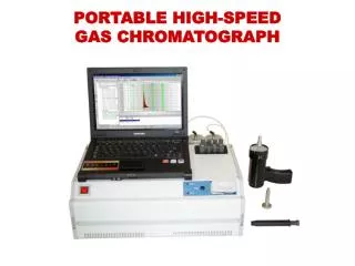
High speed chromatogram obtained with isothermal operation (30oC) for 37 sec followed by a 35oC/min temperature ramp to 90oC.