Download
1 / 60
620 likes | 796 Views
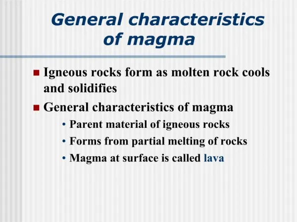
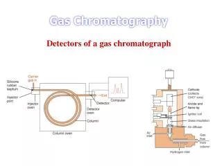
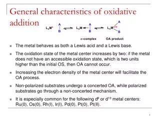
General Characteristics of Gas Detectors. Signal Creation. Charged particles traversing matter leaving excited atoms, electron or holes and ions behind. These can be detected using either excitation or ionization. Excitation.

E N D
Signal Creation Charged particles traversing matter leaving excited atoms, electron or holes and ions behind. These can be detected using either excitation or ionization. Excitation Photons emitted by excited atoms can be detected by photomultipliers or semiconductor photon detectors Ionization If an electric field is applied in the detector volume, the movement of the electrons and ions induces a signal on metal electrodes. Signals are read out using appropriate readout electronics
Signal Induction A point charge above a grounded metal plate induces a surface charge. q Total induced charge –q. q Different charge positions results in different charge distributions but the total charge stays –q. -q -q
Signal Induction for Moving Charges Segment the grounded metal plate into grounded individual strips. q The surface charge density from the moving charge does not change with respect to the infinite metal plate. q -q The charge on each strip depends on the charge position. -q If the charge is moving,current flows between the strips and ground.
Signal Theorems Placing charges on a metal electrodes results in certain potentials. A different set of charges results in a different set of potentials. Reciprocity Theorem
Signal Theorems Charge induced on an electrode is independent of the actual path. Once all charges have arrived at the electrodes, the total induced charge in the electrodes is equal to the charge that has arrived at this electrode. If one electrode encloses all the others, the sum of induced currents is always zero.
Charge Generation in a Gas Amount of ionization produced in a gas is not very great. A minimum ionizing particle (m.i.p.) typically produces 30 ion pairs per cm from primary ionization in commonly used gases (e.g. Argon) The total ionization is ~100 ion pairs per cm including the secondary ionization caused by faster primary electrons. Primary ionization Secondary ionization
Charge Collection Cathode Charge is produced near the track. Electric Field Apply an electric field to move charge to electrodes. Charge is accelerated by the field, but loses energy through collisions with gas molecules. Overall, steady drift velocity of electrons towards anode and positive ions towards the cathode. Anode
Ion Mobility Ions drift slowly because of their large mass and scattering cross-section. Similar spectrum to the Maxwell energy distribution of the gas molecules. Average drift velocity (W+) increases with the field strength (E) and decreases as the gas pressure, P, increases. A pressure increase leads to a shorter mean free path (distance during which an ion is accelerated before losing its energy in a collision). The ion mobility, μ+, defined as μ+=W+(P/E), is constant for a given ion type in a given gas.
Electron Drift Velocity The dependence of the electron drift velocity on the electric field varies with the type of gas used.
Electron Diffusion Electron longitudinal (dashed) and tranverse (solid) diffusion.
Ionization Chamber Geometry Cathode Parallel Plate Ionization Chamber Anode Anode wire Cylindrical Ionization Chamber Circular Cathode
Charge Multiplication At sufficiently high electric fields (100kV/cm) electrons gain energy in excess of the ionization energy, which leads to secondary ionization, etc. Townsend Coefficient Amplification/Gas Gain
Townsend Coefficient Computed values of the Townsend coefficient as a function of the electric field for different gases.
Avalanche Number of electrons and ions increases exponentially and quickly forms an avalanche. Positive Ions Electrons move more rapidly than ions and development a tight bunch at the head of the avalanche. Electrons: close to the wire Ions move significantly more slowly and have typically not moved from their original position when the electrons reach the anode. Anode wire
Types of Avalanches Proportional region: A=103-104 LHC Semi-proportional region: A=104-106 Saturation region: A > 108 (independent of the number of primary electrons) 1970’s Streamer region: A > 107 Avalanche along the particle track Limited Geiger region: Avalanche propagated by UV photons 1950’s Geiger region: A = 108 Avalanche along the entire wire
Proportional Counters Space charge effects arise when the electron and ion density is so large that they modify significantly the electric field locally and reduce the ionization probability. For low gains, this is unimportant and the size of the signal charge is proportional to the initial ionization. A detector operated in such a way is called a proportional counter.
Time Development of a Signal Electron avalanche occurs very close to the wire, with first multiplication occuring ~2x the wire radius. Electron move to the wire surface very quickly (<<1ns), but the ions drift to the tube wall more slowly (~100 μs). Characterized by a fast electron spike and a long ion tail Total charge induced by the electrons amount to only ~1-2 % of the total charge.
Properties of Gases Properties of commonly used gases
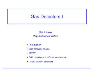
Introduction Particle physics experiments rely on the detection of charged and neutral particles by gaseous electronics A suitable gas mixture within an electric field between electrodes detects charged particles Ionizing radiation passing through liberates free charge as electrons and ions moving due to the electric field to the electrodes. The study of the drift and amplification of electrons in a uniform (or non-uniform field) has been an intensive area of research over the past century.
Requirements for Gas Mixtures • Fast: an event must be unambiguously identified with its bunch crossing • Leads to compromise between high drift velocity and large primary ionization statistics • Drift velocity saturated or have small variations with electric and magnetic fields • Well quenched with no secondary effects like photon feedback and field emission: stable gain well separated form electronics noise • Fast ion mobility to inhibit space charge effects
Electron-Ion Pair Production in a Gas An ionizing particles passing through a gas produces free electrons and ions in amounts that depend on the atomic number, density and ionization potential of the gas and energy and charge of the incident particle Np: number of primary electron pair per cm. Nt: total number of electron ion pairs (from further ionization)
Electron Transport Properties With no electric field, free electrons in a gas move randomly, colliding with gas molecules with a Maxwell energy distribution (average thermal energy 3/2 kT), with velocity v vd When an electric field is applied, they drift in the field direction with a mean velocity vd Energy distribution is Maxwellian with no field, but becomes complicated with an electric field
Noble Gases Electrons moving in an electric field may still attain a steady distribution if the energy gain per mean free path << electron energy Cross-section for electron collisions in Argon Momentum transfer per collision is not constant. Electrons near Ramsauer minimum have long mean free paths and therefore gain more energy before experiencing a collision. Drift velocity depends on pressure, temperature and the presence of pollutants (e.g. water or oxygen)
Poly-atomic gases Electron collision cross-sections for CO2 Poly-atomic molecular and organic gases have other modes of dissipating energy: molecular vibrations and rotations In CO2vibrational collisions are produced at smaller energies (0.1 to 1 eV) than excitation or ionization Vibrational and rotational cross-sections results in large mean fractional energy loss and low mean electron energy Mean or ‘characteristic electron energy’ represents the average ‘temperature’ of drifting electrons
Electron Diffusion Electrons also disperse symmetrically while drifting in the electric field: volume diffusion transverse and longitudinally to the direction of motion In cold gases, e.g. CO2, diffusion is small and the drift velocity low and unsaturated: non-linear space-time relation vd Warm gases, e.gAr, have higher diffusion. Mixing with polyatomic/organic gases with vibrational thresholds between 0.1 and 0.5 eV reduces diffusion
Lorentz Angle B Due to the deflection effect due to a B field perpendicular to the E field, the electron moves in a helical trajectory with lowered drift velocity and transverse dispersion F The Lorentz angle is the angle the drifting electrons make with the electric field Large at small electric field but smaller for large electric fields θ Linear with increasing magnetic field Gases with low electron energies have small Lorentz angle
Properties of Helium Helium-Ethane Lorentz Angle for Helium-Isobutane Drift Diffusion
Neon Longitudinal Diffusion Constant for Ne-CO2 mixtures
Diffusion in Argon Transverse Diffusion in Ar-DME mixture Transverse Diffusion in Ar-CH4 No B field With B field
Argon Lorentz Angle in Ar/CO2 Drift Velocity for Pure Argon Possible gas for single photon detectors
Xenon Xenon-CO2 In medical imaging, the gas choice is determined by spatial resolution: CO2 added to improve diffusion Pure Xenon
DME Transport Parameters for Pure DME Low diffusion characteristics and small Lorentz angles used to obtain high accuracy
Lorentz angle in DME-based mixtures • Introduced as a better photon quencher than isobutane. • Absoption edge of 195nm: stable operation with convenient gas multiplication factors • High gains and rates without sparking.
Townsend Coefficient Mean number of ionizing collisions per unit drift length Helium-Ethane DME/CO2
Ion Transport Properties Ion drift velocity Electric field pressure Constant up to rather high fields
Pollutants Pollutants modify the transport parameters and electron loss occurs (capture by electro-negative pollutants) The static electric dipole moment of water increases inelastic cross-section for low energy electrons thus dramatically reducing the drift velocity Mean electron capture length Electron capture phenomenon has a non negligible electron detachment probability
Geiger-Muller Counter 1928 Tube filled with a low pressure inert gas and an organic vapor or halogen and contains electrodes between which there is a voltage of several hundred volts but no current. Anode is a wire passing through it. Cathode is the walls. Avalanches in a Geiger Discharge Ionising radiation passing through the tube ionizes the gas. The free electrons are accelerated by the field. The avalanche begins as these in turn ionise more. Cathode UV photon Anode wire Cathode
Multiwire Proportional Chamber Invented by Georges Charpak in 1968. Nobel Prize in 1992.
MWPC The particle ionizes the gas producing electrons and free ions. The liberated electrons move rapidly move towards the anode wire and the ions towards the cathode plans More electrons are liberated which in turn ionise the gas. An avalanche of charges is produced giving rise to and electric pulse on the anode wire.
MWPC Grid of parallel thin anode wires between two cathode planes. Electrons drift to the anodes and are amplified in avalanche. Drift of ions produced in the avalanche induces a negative charge on the wire and positive charges on surrounding electrodes. Positive induced charge on adjacent wires overcomes the negative charge due to the large capacitance between the wires
Two-Dimensional Readout An MWPC with the cathode strips perpendicular to the wires. Charge profile recorded on both anodes and cathodes. Centre of gravity provides X and Y projections: Xi;Yi: Strip coordinates Qi(X), Qi(Y): Charge on strips Q(X), Q(Y): Total Charge 2D readout essential for medical imaging applications.
Applications of MWPCs Low dose X-ray digital radiography scanner based on the MWPC Applications include crystal diffraction, beta chromatography and dual energy angiography Film of congenital hip dislocation in a 7-year old boy. Satisfactory visualization of femoral architecture and bone structure
Applications in Medical Imaging Activity in a vasopressine-labelled rat’s brain (from CERN-Geneva hospital). E. Tribollet et al, Proc. Natl. Acad. Sci. USA 88(1991) 1466 Regional uptake of deoxyglucose in a dog’s heart M.G. Trivelli et al, Cardiovasclar Res. 26(1992) 330
Drift Chambers D An alternating sequence of wires with different potentials, there is an electric field between the ‘sense’ and ‘field’ wires. The electrons move to the sense wires and produces an avalanche which induces a signal read out by the electronics. The time between the passage of the particle and the arrival of the electrons is measured measure of the particles position. Can increase the wire distance to save electronics channels.
Typical Geometries of Drift Chambers W. Klempt. Detection of Particles with Wire Chambers, Bari ‘04
Straws If a single wire breaks in an MWPC the entire detectors is impacted. A solution is to replace the volume, with arrays of individual single-wire counters, known as straws. Typically a wire is strung between two supports within a thin straw (either metallic or with the internal surface coated with a metal) Portion of the ATLAS TRT End Cap
MDTs The ATLAS barrel muon spectrometers uses Monitored Drift Tubes. These reconstruct tracks to 100 μm accuracy.