Download
1 / 20
240 likes | 523 Views
FOUR BIT CARRY LOOK AHEAD ADDER. SUBMITTED BY: MILAN PATNAIK SHANTHI TENNETI DURGA L NALLARI ADVISOR: PROF. DAVID PARENT DATE : 12-06-2004. Agenda. Abstract Introduction why Theory of operation Project (Experimental) Details Results Cost Analysis Conclusions. Abstract.

E N D
FOUR BIT CARRY LOOK AHEAD ADDER SUBMITTED BY: MILAN PATNAIK SHANTHI TENNETI DURGA L NALLARI ADVISOR: PROF. DAVID PARENT DATE : 12-06-2004
Agenda • Abstract • Introduction • why • Theory of operation • Project (Experimental) Details • Results • Cost Analysis • Conclusions
Abstract • We designed a 4-bit carry look ahead adder that operates at 263 MHz and uses 4.37W (3.06mW/sqcm) of Power and occupies an area of 404m x 353m
Introduction • Most widely used design for high speed adders. - explicit arithmetic operations - computing physical addresses in most modern CPUs. - used in digital systems where full fledged CPUs are superfluous. • Speed of various digital systems significantly influenced by speed of adders.
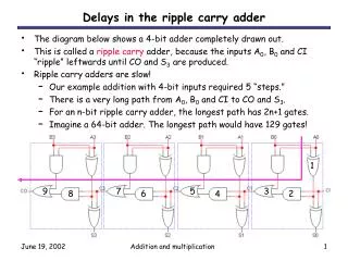
Theory of operation • Carry values calculated independently (determines carry ahead of time) • Propagate and Generate terms: Gi = Ai + Bi and Pi= Ai XOR Bi • Then outputs can be summarized as, Si=Pi xor Ci & Ci+1=Gi +PiCi C1:Previous carry C2 = G1 + P1C1 C3 = G2+P2G1+P2P1C1 C4=G3+P3G2+P3P2G1+P3P2PC1 C5=G4+P4G3+P4P3G2+P4P3P2C2 1BIT FULL ADDER
Project Details • Initial hand calculations • Block level schematics • Block level layouts • Total schematic • Integration of the block level layouts • Circuit extraction & LVS • Post extraction simulations
Cg of Driver MUX (master ff)= 19.93fF which matches the Cg =20fF assumption.
DFF timings T hold (rise)=0.5n T hold (fall)=0.48n T setup (rise)=0.73n T setup (fall)=0.64n
Period= 4ns Simulations… Period=3.5ns
Cost Analysis • Time spent on the various phases of the project: • verifying logic(2 days) • Hand calculations(1 week) • Layout(4 days) • Modifying layout(2 days) • post extracted simulations(1 day)
Lessons Learned • Start working as early as possible!! • Plan the layout beforehand for an efficient design. • Use the same cell heights for all the blocks.
Summary • Our CLA operates at 263 MHz of Clock Frequency, uses 4.37W of Power and occupies an area of 404m x 353m • The adder can be designed with lesser area and power consumption with a more organized Layout
Acknowledgements • Thanks to Cadence Design Systems for the VLSI lab • Thanks to Synopsys for Software donation • Thanks to Professor David Parent • Thanks to EE166 Classmates