Download
1 / 28
920 likes | 2.61k Views
Components of HVAC System. While these five loops can be used to describe virtually any HVAC system, not every system uses all five loops. The purpose of this period is to provide a method for understanding the components of different types of HVAC systems.

E N D
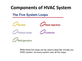
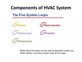
Components of HVAC System While these five loops can be used to describe virtually any HVAC system, not every system uses all five loops.
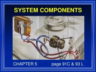
The purpose of this period is to provide a method for understanding the components of different types of HVAC systems. • The premise of this method is that any HVAC system can be dissected into basic subsystems. • These subsystems will be referred to as “loops.” • There are five primary loops that can describe virtually any type of HVAC system.
The first loop is the airside loop, and the first component of this loop is the conditioned space. • The first two comfort requirements mentioned were dry bulb temperature and humidity. • In order to maintain the dry-bulb temperature in the conditioned space, heat (referred to as sensible heat) must be added or removed at the same rate as it leaves or enters the space. • In order to maintain the humidity level in the space, moisture (sometimes referred to as latent heat) must be added or removed at the same rate as it leaves or enters the space.
Supply Fan and Filter • The othercomponent of the airside loop is a supply fan that delivers the supply air (SA) to the space.
A heat exchanger, commonly known as a cooling coil, is often used to cool and dehumidify the supply air before it isdelivered to the space. • A typical cooling coil includes rows of tubes passing through sheets of formed fins. • A cold fluid, either water or liquid refrigerant, enters one header at the end of the coil and then flows through the tubes, cooling both the tubes and the fins.
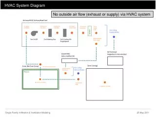
Fan-Coil Unit • A simple example of the airside loop is a fan-coil unit. • Return air from the space is drawn into the unit at the base and can be mixed with outdoor air that enters through a separate damper in the back of the unit. • This mixed air passes through a filter, a supply fan, and a cooling coil before being discharged from the top of the unit, directly into the conditioned space.
Central Air Handler • Another example of the airside loop is a central air-handling system. • A central air handler is typically installed outside of the conditioned space, possibly on the roof or in a dedicated mechanical room. • Return air from the space is drawn into the unit through the return-air dampers and mixes with outdoor air that enters through another set of dampers. • This mixed air passes through the filters, the supply fan, and the cooling coil before being discharged from the air handler.
Unlike the example fan-coil unit that was installed in the conditioned space, the central air handler needs a method for delivering the supply air to the conditioned space(s).
Supply-Air Distribution System • A supply-air distribution system, typically constructed of sheet-metal ducts, fittings, and diffusers, is used to direct the supply air from the central air handler to one or more conditioned spaces. • From each VAV terminal unit, the supply air travels through a section of flexible duct to remotely located diffusers. • Diffusers are used to distribute the supply air effectively to the conditioned space. • Proper air diffusion is an important comfort consideration, especially in VAV systems, to avoid dumping cold supply air on the occupants of the space.
The plenum is the space between the ceiling and the roof, or floor, above.
Chilled-Water Loop • In the airside loop, a cooling coil is used to cool and dehumidify the supply air. • As mentioned, the cold fluid flowing through the tubes of the coil may be either water or liquid refrigerant. • Systems that use water flowing through the cooling coil also contain a chilled-water loop.
Evaporator • It has also been mentioned that the water flowing through the cooling coil must be colder than the air passing through it. • This heat exchanger, called an evaporator, isone component of the refrigeration (cooling) equipment.
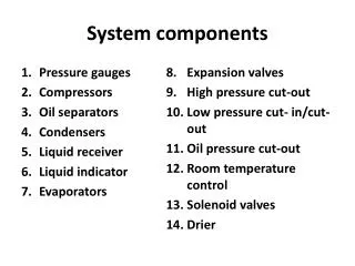
Pump and Control Valve • The other component of the chilled-water loop is a pump that moves water around the loop. • This pump needs to have enough power to move the water through the piping, the evaporator, the tubes of the coil, and any other accessories installed in the chilled-water loop. • Similar to the airside loop, the chilled-water loop responds to changing cooling loads by varying either the temperature or the quantity of water delivered to the cooling coil. • The most common method, however, is to vary the quantity of water flowing through the cooling coil by using a control valve.
As the cooling load decreases, the modulating control valve reduces the rate of chilled-water flow through the coil, decreasing its cooling capacity.
An example of a system that does not use the chilled-water loop is one that uses a packaged rooftop air conditioner
Heat-Rejection Loop • The fourth loop is the heat-rejection loop. • In the refrigeration loop, the condenser transfers heat from the hot refrigerant to air, water, or some other fluid. • In a water-cooled condenser, water flows through the tubes while the hot refrigerant vapor enters the shell space surrounding the tubes. • Heat is transferred from the refrigerant to the water, warming the water. • The water flowing through the condenser must be colder than the hot refrigerant vapor. • When a water-cooled condenser is used, this heat exchanger is typically either a cooling tower or a fluid cooler (also known as a dry cooler).
Controls Loop • The fifth, and final, loop of the HVAC system is the controls loop. • Each of the previous four loops contains several components. • Each component must be controlled in a particular way to ensure proper operation. • Typically, each piece of equipment (which may be comprised of one or more components of a loop) is equipped with a unit-level, automatic controller. • In order to provide intelligent, coordinated control so that the individual pieces of equipment operate together as an efficient system, these individual unit-level • controllers are often connected to a central, system-level controller.
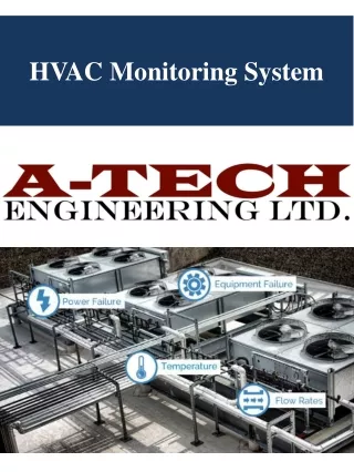
Finally, many building operators want to monitor the system, receive alarms and diagnostics at a central location, and integrate the HVAC system with other systems in the building. These are some of the functions provided by a building automation system (BAS).