HVAC System Design
HVAC System Design. PES Institute of Technology. Objective. Goal: To develop an automotive air-conditioning system that is smaller and lighter than with conventional technology.

HVAC System Design
E N D
Presentation Transcript
HVAC System Design PES Institute of Technology
Objective Goal:To develop an automotive air-conditioning system that is smaller and lighter than with conventional technology. The Challenge:The system must be capable of keeping a temperature of 22˚C inside a stationary black vehicle with four occupants, with an outside temperature of 40˚C. Also, the system must be an efficient heating system, keeping an internal temperature of 15˚C with an outside temperature of 0˚C.
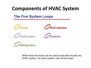
H.V.A.C • H.V.A.C – Heating, Ventilation and Air Conditioning system • The HVAC regulates: • Room Temperature • Humidity • Air Quality • Air Flow
3 2 4 1 Enthalpy kJ/kg Refrigeration Cycle Vapour Compression Cycle
Design Parameters & Considerations • Heat Load on the HVAC = 5.287 kW • Cabin Relative Humidity = 40% • Evaporator Temperature = 4°C • Refrigerant Used = R134a • Refrigeration Cycle : Vapour Compression • Cabin design – cooling and heating requirements • Temperature and Humidity range • Placement of Vents and Ducts • Space considerations • Effect on car performance • Efficiency • Environmental Impact
Cycle Analysis & Heat Load Assumptions: • Compression process is isentropic. • No pressure losses in piping. • Condenser temperature = 46°C. • Evaporator Temperature = 4° C. • Refrigerant is not sub cooled. Heat Load Calculations: • Heat due to opaque surfaces = 3598.2 W • Heat due to fenestration = 1229.66 W • Internal Loads ( human ) = 460 W Total Load = 5.287 kW
Results • Evaporator Pressure = 3.38 bar • Condenser Pressure = 11.9 bar • Heat Load = 5.287 KW • Condenser Cooling Load= 6.308 KW • Compressor Work = 1.02 KW • Mass Flow Rate = 1.94 l/min
Selection Basis • Scroll Compressors – Compact design and High Volumetric Efficiency ( around 98% ). • Refrigerant R134a – Minimized environmental impact. • Plate-Fin Heat Exchanger- Compact size, Higher heat transfer capability. • Simple design incorporated to minimize cost.
Compressor • Heart of the system, belt driven pump that fastened to engine. • Responsible for compressing and transferring refrigerant. • Two interleaved scrolls with involute geometry. • One scroll fixed while the other orbits eccentrically to compress fluid • Advantage: • Very high volumetric efficiency (almost 98%) • Lesser Noise and lighter compared to rotary compressor.
Condenser • Responsible for heat dissipation • The condenser is designed to radiate heat. • Located in front of the radiator • Require good air flow when system is in operation • Plate fin type heat exchanger with micro channels used. • Very compact and better heat transfer capability. • Hot compressed refrigerant vapour cools at constant pressure to liquid. • Overall Heat Transfer Coefficient = 92 W/m2K • Area = 6.87 m2
Accumulator • Depending on the vehicle, the A/C system will either have a receiver dryer or an accumulator. • Components contain a desiccant, chemical that attracts moisture. • Prevents formation of corrosive acids on mixture of water and acid. • Also act as temporary storage for refrigerant to prevent starving of evaporator
Evaporator • Heat absorption component. • Used remove heat from the inside of vehicle. • Secondary benefit - dehumidification. • Unconditioned air passes through a filter before entering the evaporator. • Plate-fin evaporator with micro channels used. • Overall heat transfer coefficient = 98 W/m2K • Area calculated = 3.04 m2 • Fan Flow Rate = 90 l/s
Looking Ahead • Finalize and validate results based on inputs from other teams. • Improvise on the current design and form a cost effective solution. • Documentation and reports.