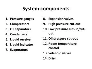
SYSTEM COMPONENTS
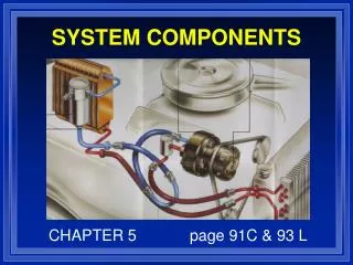
SYSTEM COMPONENTS. CHAPTER 5 page 91C & 93 L. OBJECTIVES. IDENTIFY AND COMPARE THE STATE OF REFRIGERANT IN EACH SECTION OF A/C SYSTEM. EXPLAIN PURPOSE OF SYSTEM COMPONENTS. COMPARE THERMOSTATIC EXPANSION VALVE TO FIXED ORIFICE VALVE. 93C & 91L. ORIFICE TUBE SYSTEM. EXPANSION VALVE SYSTEM.

SYSTEM COMPONENTS
E N D
Presentation Transcript
SYSTEM COMPONENTS CHAPTER 5 page 91C & 93 L
OBJECTIVES • IDENTIFY AND COMPARE THE STATE OF REFRIGERANT IN EACH SECTION OF A/C SYSTEM. • EXPLAIN PURPOSE OF SYSTEM COMPONENTS. • COMPARE THERMOSTATIC EXPANSION VALVE TO FIXED ORIFICE VALVE. 93C & 91L
Compressor • Refrigerant Pump • Increases Pressure and Temperature • Several Types • Separates High and Low sides of system • Oil is stored in crankcase (sump)
Compressor Malfunctions • Malfunctions evident following ways; • Noise • Seizure • Leaks • High inlet and low discharge pressure
Discharge Hose • CONTAINS HIGH PRESSURE. • SYNTHETIC RUBBER WITH NYLON BARRIER LINING. • 13/32 ID. • PREFORMED METAL ENDS WITH FITTINGS.
96C & 97C 109L Condenser • Liquefies heat laden vapor. • Receives Maximum Air flow. • Hot vapor enters top of condenser. • Hot Liquid leaves bottom of condenser. • Refrigerant flows through condenser coils and transfers heat to coils and fins. • Fins transfer heat to air passing over them.
Conventional Tube and Fin • Parallel Two Path. • Mechanically expanded tube to fin joints. • Circular Tubes.
Multi-Louver Fin Design • Manifolded Multi-path refrigerant flow.
Serpentine Tube and Center Condenser • Brazed tube to fin joints. • Flat Tubes. • Parallel two path flow.
100C & 110L Evaporator • Dehumidifies the airstream. • Under ideal conditions, refrigerant boils to complete saturation 3/4 of the way through Evaporator. • Flooded evaporator means is full of liquid refrigerant with no room for expansion. • Starved evaporator means all refrigerant is boiled in the first quarter of the evaporator.
96C & 110L Receiver Drier • Located between condenser and metering device • Assures only liquid reached expansion valve • Contains a chemical drying agent (Desiccant)
103C 98L -102L Hoses and Lines • NOTICE: Do not use wormgear style clamps for repairing leaks in Nylon barrier hose fittings. Always repair Nylon barrier hose with the appropriate bubble style crimp fitting.
Liquid Lines • Condenser to the metering device • 5/16 or 1/4 inch ID. • Made of rubber, nylon, copper, steel or aluminum. • Contains high pressure liquid! • Has sight glass
Thermostatic Expansion Valve • Located on inlet side of evaporator. • Used to control evaporator temp. • Variable orifice can vary on pressure, temperature or both. • Can malfunction in open or closed position. 98C 102L
H-Valve • Is a Expansion Valve: Chrysler 1979 and later. • Has internal sensing bulb for low side temperature. • Low Pressure Cut Out Switch for low R-12 Charge. • Thermostatic Switch Senses Evap temp to control clutch operation. 99C & 104L
Valves In Receiver (VIR) • Three different components • TXV • Receiver/Drier • Pilot-operated-absolute suction throttling valve • Compressor runs all the time. Page 95C
Orifice Tube • Calibrated Restrictor • Different color = different Orifice size. • Mesh Filter Screen. • Meters refrigerant into evaporator as low pressure liquid. 100C & 105L - 107L
Accumulator • Located between evaporator and compressor. • Primary function is to separate the vapor from the liquid and oil. • Location for desiccant. 102C & 107L