Download
1 / 23
250 likes | 478 Views
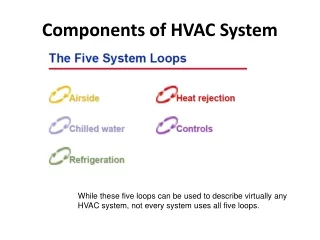
This document provides a detailed HVAC system diagram that includes aspects of air flow management, heating, cooling, and dehumidification. It outlines various nodes in the system, including supply, demand, and exhaust nodes, as well as energy calculations for infiltration and ventilation. Utilizing ASHRAE standards, it incorporates both natural and mechanical ventilation strategies and models, demonstrating flow rates and system efficiencies for residential applications. This document serves as a pivotal reference for those engaged in HVAC design and energy modeling.

E N D
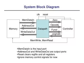
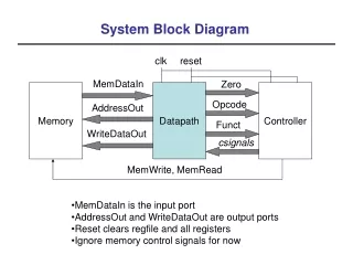
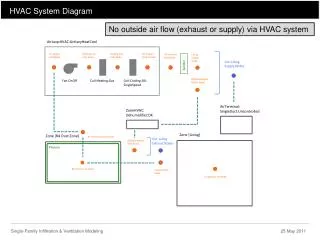
HVAC System Diagram No outside air flow (exhaust or supply) via HVAC system AirLoopHVAC:UnitaryHeatCool Air Supply Inlet Node Heating Coil Inlet Node Cooling Coil Inlet Node Air Supply Outlet Node Air Demand Inlet Node Living Supply Node List: Living Supply Nodes Splitter DXDehumidifier Outlet Node Coil:Cooling:DX: SingleSpeed Fan:OnOff Coil:Heating:Gas AirTerminal: SingleDuct:Uncontrolled ZoneHVAC: Dehumidifier:DX Zone [Living] Zone [RA Duct Zone] Air Demand Outlet Node List: Living Exhaust Nodes DXDehumidifier Inlet Node Plenum RA Plenum Air Node Living Return Node Living Zone Air Node Single-Family Infiltration & Ventilation Modeling 25 May 2011
HVAC System Diagram – with ERV Outside air flow (supply and exhaust) via ERV AirLoopHVAC:UnitaryHeatCool Air Supply Inlet Node Heating Coil Inlet Node Cooling Coil Inlet Node Air Supply Outlet Node Air Demand Inlet Node Living Supply Node List: Living Supply Nodes ERV Supply Fan Outlet Node ERV Supply Fan Inlet Node ERV Outside Air Inlet Node Splitter Fan:OnOff DXDehumidifier Outlet Node Coil:Cooling:DX: SingleSpeed Fan:OnOff Coil:Heating:Gas Living Exhaust Node ERV Exhaust Fan Outlet Node ERV Exhaust Fan Inlet Node Fan:OnOff AirTerminal: SingleDuct:Uncontrolled ZoneHVAC: Dehumidifier:DX Zone [Living] Zone [RA Duct Zone] Air Demand Outlet Node List: Living Exhaust Nodes DXDehumidifier Inlet Node Plenum RA Plenum Air Node Living Return Node Living Zone Air Node Single-Family Infiltration & Ventilation Modeling 25 May 2011
Infiltration Calculations EnergyManagementSystem:Program, InfiltrationProgram, Set Tdiff = Tin - Tout, Set DeltaT = @Abs Tdiff, Set c =0.0806596739779895, Set Cs =0.0808179140957512, Set Cw =0.151714102844197, Set n =0.67, Set sft =0.5039400176752, Set Qn = (((c*Cs*(DeltaT^n))^2)+(((c*Cw)*((sft*Vwind)^(2*n)))^2))^0.5, !Section above: !This is equation 41 + equation 42 from ASHRAE Fundamentals 2005 Ch 27 !"Enhanced Model. This section presents a simple, single-zone approach !to calculating air infiltration rates in houses based on the AIM-2 model !(Walker and Wilson 1998). The airflow rate due to infiltration is !calculated using: ! Qs = c * Cs * DeltaT^n (41) ! Qw = c * Cw (sU)^2n (42) ! where: Qs = stack airflow rate, m3s ! Qw = wind airflow rate, m3/s ! c = flow coefficient, m3/(s/Pa^n) ! Cs = stack coefficient, (Pa/K)^n ! Cw = wind coefficient, (Pa-s^2/m^2)^n ! s = shelter factor ! Several assumptions made when calculating Cs, Cw, s ! including: n = 0.67 ! Equation (39) then describes superposition for the total infiltration rate: ! Q = ((Qs^2)+(Qw^2))^0.5 Set Tdiff = Tin - Tout, Set DeltaT = @Abs Tdiff, Set QWH = WH_sch*0.025029576, Set Qrange = Range_sch*0.04719, Set Qdryer = Clothes_dryer_sch*0.04719, Set Qbath = Bath_sch*0.04719, Set Qu = QWH+Qrange+Qbath+Qdryer+DuctLeakOAMakeupFlowRate, Set Qb = 0, Set faneff_wh =0.28314, Set WholeHouseFanPowerOverride= (QWH*300)/faneff_wh, Set faneff_sp =0.28314, Set RangeHoodFanPowerOverride = (Qrange*300)/faneff_sp, Set BathExhaustFanPowerOverride = (Qbath*300)/faneff_sp, Set Infilflow = ((Qu^2) + (Qn^2))^0.5, Set InfMechVent = Qb + Infilflow; !Two lines above described by Equation (43) in ASHRAE Fundamentals 2005 Ch 27 !Says that you can combine residential infiltration and mechanical ventilation flows: ! Qcomb = Qbal + ((Qunbal^2)+(Qinfil^2)) Parameters to change infiltration rates Qn = infiltration flow Qu = unbalanced exhaust flow = QWH + Qrange + Qdryer + Q bath + DuctLeakage QWH = Whole house exhaust fan Qrange = Kitchen range hood Qbath = Bath point exhaust Qdryer = Dryer exhaust DuctLeakage = Calculated from DuctLeakageProgram Qb = balanced ventilation = 0 InfMechVent = Total flow Single-Family Infiltration & Ventilation Modeling 25 May 2011
Ventilation Components & Schedules Building America House Simulation Protocol, pg 16: “Additional air exchange whole-house mechanical ventilation shall be calculated assuming a single point exhaust ventilation system with the same ventilation rate used for the NCTH, up to a maximum value consistent with the rate recommended by ASHRAE 62.2. Whole-house mechanical ventilation air shall be added to the natural infiltration rate in quadrature, assuming no heat recovery. Ventilation fan energy use for the Benchmark shall be calculated using a fan efficiency of 0.5 W/cfm. In addition to whole-house ventilation, the Benchmark shall include a kitchen range hood, spot ventilation fan in each bathroom, and exhaust from the clothes dryer. The flow rates of the kitchen and bathroom fans shall be the same as those in the NCTH, and their efficiency shall be assumed to operate 60 min/day (between 6:00 pm and 7:00 pm), and each bathroom fan (including those in central restrooms) is assumed to operate 60 minutes per day (between 7:00 am and 8:00 am). The clothes dryer fan will operate for 60 minutes per day between 11:00 am and 12:00 pm. Interactive effects between these spot exhaust ventilation fans and natural infiltration shall be included in the analysis.” Single-Family Infiltration & Ventilation Modeling 25 May 2011
ASHRAE 62.2 Ventilation Requirements ASHRAE 62.2-2003, Section 4.1: “A mechanical exhaust system, supply system, or combination thereof shall be installed for each dwelling unit to provide whole-building ventilation with outdoor air each hour at no less than the rate specified in Table 4.1a and Table 4.1b, or, equivalently, Equations 4.1a and 4.1b, based on the floor area of the conditioned space and number of bedrooms.” Qfan = fan flow rate in L/s; Afloor = floor area in m2; Nbr = number of bedrooms For Nbr = 3, Afloor = 222 m2 (2400 ft2): Qfan = 25.1 L/s = 0.025 m3/s = 54 cfm Single-Family Infiltration & Ventilation Modeling 25 May 2011
Modeling Results – Exhaust Flows – Summer Design Day Single-Family Infiltration & Ventilation Modeling 25 May 2011
Modeling Results – Qu & Qn – Summer Design Day Single-Family Infiltration & Ventilation Modeling 25 May 2011
Modeling Results – Total Flow – Summer Design Day Single-Family Infiltration & Ventilation Modeling 25 May 2011
Modeling Results – Hours not meeting ASHRAE 62.2-2003 Single-Family Infiltration & Ventilation Modeling 25 May 2011
Natural Ventilation Calculations EnergyManagementSystem:Program, NaturalVentilationProgram, Set Tdiff = Tin - Tout, Set DeltaT = @Abs Tdiff, Set Phiin = @RhFnTdbWPb Tin Win Pbar, ! RhFnTdbWPb: Calculates RH (fraction) from DB, Humidity Ratio, Barometric Pressure Set Hin = @HFnTdbRhPb Tin PhiinPbar, ! HFnTdbW: Calculates Enthalpy of moist air (J/kg) from DB and Humidity Ratio Set NVArea =12006.190854504, !Not clear how this number is determined, but it is cm^2 Set Cs =0.0001792604077892, Set Cw =0.0002821728237939, Set MaxNV =2.8993536, Set SGNV = (NVAvail*NVArea)*((((Cs*DeltaT)+(Cw*(Vwind^2)))^0.5)/1000), !Line above based on equation (40) from ASHRAE Fundamentals 2005 Ch 27 !This is the basic model for calculating the airflow rate due to infiltration ! Q = AL/1000((Cs*DeltaT)+(Cw(U^2))^0.5 ! where: Q = airflow rate m3/s ! AL = effective air leakage area, cm2 ! DeltaT = Avg indoor-outdoor temp difference, K ! Cw = wind coefficient ! U = avgwindspeed measured at local weather station If Wout < 0.0155 && Phiin < 0.70 && Tin > NVSP, !Line above sets outdoor conditions for nat vent !Wout is Outdoor Humidity Ratio; Phiin is RH; Tin is Zone MAT; NVSP is NatVentTemp Schedule Value. Set NVadj1 = (Tin - NVSP)/(Tin - Tout), Set NVadj2 = @Min NVadj1 1, Set NVadj3 = @Max NVadj2 0, Set NVadj = SGNV*NVadj3, Set NatVentFlow = @Min NVadjMaxNV, Else, Set NatVentFlow = 0, EndIf; Qn = infiltration flow Qu = unbalanced exhaust flow = QWH + Qrange + Qdryer + Q bath + DuctLeakage QWH = Whole house exhaust fan Qrange = Kitchen range hood Qbath = Bath point exhaust Qdryer = Dryer exhaust DuctLeakage = Calculated from DuctLeakageProgram Qb = balanced ventilation = 0 InfMechVent = Total flow Single-Family Infiltration & Ventilation Modeling 25 May 2011
Modeling Results –BEOpt Vent Options Single-Family Infiltration & Ventilation Modeling 25 May 2011
Modeling Results –BEOptNatVent Options Single-Family Infiltration & Ventilation Modeling 25 May 2011
Modeling Results –BEOpt Slab Options Single-Family Infiltration & Ventilation Modeling 25 May 2011
Modeling Results –NatVent This report variable represents the sensible heating energy in Joules that is actually supplied by the system to that zone for the timestep reported. This is the sensible heating rate multipled by the simulation timestep. “Zone/Sys Sensible Heating (and Cooling) Energy all report the heating or cooling delivered by the HVAC system to a zone. These values are calculated by multiplying the supply air mass flow rate by the difference between the supply air temperature and the zone air temperature. This does not always indicate the operation of heating or cooling coils. For example, cooling will be reported if the supply air is cooled due to the introduction of outside air, event if all coils are off.” I/O pg. 168 Single-Family Infiltration & Ventilation Modeling 25 May 2011
Modeling Results –NatVent Single-Family Infiltration & Ventilation Modeling 25 May 2011
Modeling Results –NatVent Single-Family Infiltration & Ventilation Modeling 25 May 2011
Modeling Results –NatVent This is the total (sensible plus latent) cooling output of the DX coil in Joules over the timestep being reported. This is determined by the coil inlet and outlet air conditions and the air mass flow rate through the coil. I/O pg. 168 Single-Family Infiltration & Ventilation Modeling 25 May 2011
Modeling Results –NatVent - SFO Single-Family Infiltration & Ventilation Modeling 25 May 2011
Modeling Results –NatVent - SFO Single-Family Infiltration & Ventilation Modeling 25 May 2011
Modeling Results –MechVent (w and w/o nat vent) Single-Family Infiltration & Ventilation Modeling 25 May 2011
Modeling Results –MechVent (w and w/o nat vent) Single-Family Infiltration & Ventilation Modeling 25 May 2011
Modeling Results –MechVent (w and w/o nat vent) Single-Family Infiltration & Ventilation Modeling 25 May 2011
Modeling Results –MechVent (w and w/o nat vent) Single-Family Infiltration & Ventilation Modeling 25 May 2011