HVAC SYSTEM DESIGN
HVAC SYSTEM DESIGN. Businessmen Club. Supervisor:. Dr Salameh Abdulfattah . The students:. Ameer Khaled (10716625). Nabil abu hanih ( 10840770). Saleem Sama’neh (10716714). Tariq Ismail (10740129). The Aim of The Project.


HVAC SYSTEM DESIGN
E N D
Presentation Transcript
HVAC SYSTEM DESIGN Businessmen Club Supervisor: Dr Salameh Abdulfattah The students: • Ameer Khaled (10716625) • Nabil abu hanih (10840770) • Saleem Sama’neh (10716714) • Tariq Ismail (10740129) HVAC System
The Aim of The Project • The aim of this project is to design installation of heating, ventilation and air condition system (HVAC) for buissnessmen club in ramallah . • VRV system will be used to design air conditioning. • Water service and plumping design is required for service system inside the building • Fire protection system will used in the building HVAC System
Presentation out line • - Building Description. • - Heating And Cooling loads. • - Duct Design. • - Plumping System . • - Fire Fighting System. HVAC System
Businessmen Club clublocation City: Ramallah, Tira, Tal Es-Safa. Elevation: 840 m above sea level. Latitude: 32˚ Building face is to the south direction HVAC System
climate zone in winter -Inside and out side design condition in winter (heating): HVAC System
The Heat load Equation : 1. Q = U* A* ( Ti - To ) Vvent= n * value of ventilation Vinf= (ACH * inside volume *1000) /3600 2. Qs)vent , inf= 1.2 Vvent,inf*(Ti-To) Ql)vent , inf= 3 Vvent,inf*(Ti-To). 3. Qbuilding= Qs)cond+ Qs)v,inf + Ql)v ,inf 4. Qboiler= 1.1*Qw HVAC System
Summary for heating load HVAC System
climate zone in summer Inside and out side design condition in summer (cooling) HVAC System
Cooling Load equation : 1 ) For ceiling : Q=U*A*(CLTD)corr(CLTD)corr=(CLTD + LM) K + (25.5 – Ti )+ (To – 29.4) Where :K=0.5 light color 2) For walls : Q =U*A*(CLTD)corrWhere :K=o.65 3)For glass :Heat transmitted through glass:Q=A*(SHG)*(SC)*(CLF)Convection heat gain:Q=U*A*(CLTD)corr HVAC System
Cooling Load equation : 4 ) For people:Qs= qs*n*CLFQL= qL*n 5) For lighting: Qs= A*q*CLF6) For equipments: Qs= qs*CLFQL= qL HVAC System
Summary of cooling load HVAC System
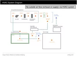
VRV SYSTEM: HVAC System
Duct design: • Design procedures: 1. The total sensible heat was calculated. 2. The Vcirculation was calculated. 3. The flow rate (CFM) was calculated. 4. Number of diffusers are calculated and distributed uniformly. 5. The initial velocity for the main duct is 5 m/s. 6. The pressure drop is depend on the initial velocity for the main duct and flow rate (CFM). 7. The main diameter is calculated. 8. The height and width of the rectangular ducts are determined from the tables. HVAC System
Sample Calculation For Duct Design HVAC System
Plumping system Plumping system consist of: Potable water system. Drainage system. Firefighting system. HVAC System
Plumbing System Total demand water :
20 20
22 22
Sample of calculation for determined number of fixture unit:
Fire Fighting Design • The net area of each floor is less than 7432 m2 (80000 ft2) that means we should use one raiser only. • The building has one raiser which takes 250 GPM and has a pipe diameter of 4". * We chose to use the standpipe system which consists of two main part: Cabinet: Diameter of the hose = 1½ ". Flow rate = 100 GPM. Pressure = 65 Psi. Land valve: Diameter = 2½ ". Flow rate = 250 GPM. Pressure = 100 Psi. HVAC System
Fire Fighting Design HVAC System
LAF = 19.21 m. LFH = 0.91 m. ΔPpump = ΔP(friction + fitting) + ΔPhead + Δpflow ΔPfriction = (ΔP/L)AF * LAF + (ΔP/L)FH * LFH = (1)(19.21) + (15)(.91) = 32.86 Psi To convert it to Pa: ΔPfriction = (32.86)*(3.3*6.8*1000/100) = (32.86)*(224.4) = 7373.784 Pa ΔP(friction + fitting) = 1.5 ΔPfriction = 1.5 *7373.784 = 11060.67 Pa. HVAC System
ΔPhead = Lhead * = 12 * 9.81 *103 = 117720 Pa. ΔPflow = 100 Psi for the landing valve. = 100*6.8*103 = 680000 Pa. ΔPpump = ΔP(friction + fitting) + ΔPhead + ΔPflow = 11060.67 + 117720 +680000 = 808.780kPa. Tank volume = (Q*Time*3.78)/1000 = (250*2*60*3.78)/1000 = 113.4 m3/hr. HVAC System