Download
1 / 34
390 likes | 648 Views
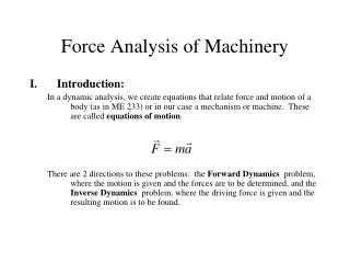
Force Analysis of Machinery. Introduction: In a dynamic analysis, we create equations that relate force and motion of a body (as in ME 233) or in our case a mechanism or machine. These are called equations of motion .

E N D
Force Analysis of Machinery • Introduction: In a dynamic analysis, we create equations that relate force and motion of a body (as in ME 233) or in our case a mechanism or machine. These are called equations of motion. There are 2 directions to these problems: the Forward Dynamics problem, where the motion is given and the forces are to be determined, and the Inverse Dynamics problem, where the driving force is given and the resulting motion is to be found.
Forward Dynamics Forward kinematics: We will call our method Kinetostatics – look for dynamic equilibrium at a specific position and time, a snapshot of the mechanism. The equations will look like: With m, a known, F unknown, or for a mechanism: The eq’s for force are linear and solved using linear algebra
Inverse Dynamics Inverse dynamics: Called the time-response problem. This solves the motion of a mechanism given the input driving force. Force example, the time history of the flight of an arrow leaving a bow. For these problems, we write equations of motion (which are now differential eqations of motion) that might look like: And solve motion as a function of time through numerical integration. For ex.
Summary Forward Dynamics: “Kinetostatics” Given motion, find required driving force and all bearing reactions • Inverse Dynamics: • “Time response” • Given input force, solve output motion as a function of time.
Motivational slide • Performing force analysis of a mechanism draws on all your modeling skills: • Mechanism modeling, position, velocity and acceleration analysis, force analysis • Goals from this section: • Learn how to carry out a force analysis (kinetostatics) • Apply to several examples in class and HW. • Create a computer model (Matlab) for force analysis and apply to a specific problem
Review of Dynamics • Newtonian mechanics: • Conservation of momentum • Force = rate of change of momentum • Action/reaction • Corollary, Euler’s Equation: • Torque = rate of change of angular momentum
Review of Dynamics • Dynamic forces: • Linear acceleration: Acceleration of pt. P: Sum forces on particle P: And integrate to solve: Result: **
Review of Dynamics • Dynamic Moments: • General layout shown in figure:
Review of Dynamics • Dynamic Moments (cont.): • Sum moments about point D for particle P, then integrate over the body: • Results: I is about c.g. • If summed about c.g. (point g)
Other points to review • 2-force member: A link is a 2FM if it satisfies 3 conditions: • It has revolutes at each end • No loads other than at the endpoints • Mass is negligible compared to the load All forces lie along direction of the link
Force Analysis Techniques • Superposition: • Given a mechanism with known position, velocity, and acceleration conditions, derive Newtons equations for dynamic equilibrium. These equations are linear in the forces and therefore Superposition principles can be applied: Inertial and applied forces on each link can be considered individually and then superposed to determine their combined effect. • This approach is good for building intuition and solving by hand. • This approach can be very long • Matrix Method • All inertial and applied forces are considered at once. The dynamic equations become coupled in the unknown forces and are solved using linear algebra techniques. • Note: Why are forces linear? • This approach is the best for computer application, therefore our method of choice.
Force Analysis Techniques • Energy method (Virtual work): • Here, only forces that do work on the mechanism are considered. An equation of conservation of energy is written that results in 1 scalar equation with 1 unknown (for a 1 dof system) • This is the easiest method if only the input force is required.
Superposition • To find driving and bearing forces using superposition, break the problem into n-1 parts. For ex. • Find Tin’ = due to forces on link n • Find Tin’’ = due to forces on link n-1 • Find Tin’’’’’’ = due to forces on link 2 • Notes: • Notation: F14 = force of link 1 on link 4 • Be careful with signs • F14=-F41, • But, remember to either switch the sign, or the direction of the vector, but not both • T=rxF
Superposition: Procedure • Break the problem into n-1 parts, n = number of links. • Start with part 1 • Draw FBD’s of the extreme link • Include all forces for Part 1 ONLY • Look for 2FM’s to reduce unknowns • Solve unknown reaction forces as 3 eq’s, 3 uk’s (in general) • 3 equations are:
Superposition: Procedure (cont.) • Move to the next link, transferring forces from the previous as, • F23=-F32 (or, changing the directions on the vectors and keeping the magnitude) • Continue to the driving link, solve for Tin’ • Move to part II • Repeat, solving Tin’’ • Continue for all parts, 1 to n-1 • Find the total reactions as: • Tin(tot) = Tin’+Tin’’+Tin’’’+ … • F12x(tot)= F12x’+ F12x’’+… • Etc. • Note, consistent directions for all the reaction forces must be maintained in all parts.
Superposition: Example Given: • P=10,45deg, R=10i, T4=5k • m2=0,m3=1,m4=sqrt2 • I2=0, I3=1, I4=1 • ag3=-1i+1j, ag4=-1j • a3=0, a4=1 Find: Tin and reactions at grd. bearings
Superposition: Example 2 • Hydraulic-powered scoop with a load in bucket (link 4)
Superposition: Example 2 • Links 2 & 4 have mass • m2 = 10 kg, I2 = 1 kgm^2 • m4 = 100 kg I4 = 10 kgm^2 • Consider the cylinder, 5 as a 2 FM. Given the following motion information, find the input cylinder force and the bearing reactions at points O2 and O5. • Motion info: • w2=1, a2=1 rad/s^2 w4=1, a4=1 rad/s^2 • Vg2=-1i+0j m/s Vg4=-1i+1j m/s • Ag2=01i-1j m/s^2 Ag4=-2i+0j m/s^2 • Vp=2j • Force on bucket: • P = 100N
Force Analysis using the Matrix Method In the matrix method, equations of dynamic equilibrium are written for FBD’s of all the links in the mechanism w/ all internal and external forces included. This results in a coupling of the unknown forces. However, the equations are linear in these forces and may be solved using linear algebra techniques. For example: Solving forces: Known motion info Known coefficients Unknown forces and torques
Matrix Method (cont.) In a general mechanism, there may be anywhere from 10 to 30 unknown forces to solve. Solve in Matlab (or other computer program) This method will be demonstrated first on a four-bar linkage.
Matrix Method: Example 1 The figure above shows a general 4-bar linkage. The center of mass of each link is shown, as well as the input torque on link 2, and an applied torque (T4) on link 4.
Matrix Method: Example 1 (cont.) Here, we have included some additional vectors to help define our problem. This leads to the following notation: gi = center of mass of link i jti = joint i rij = vector from cm of i to jt. j Fij = vector force of i on j
Matrix Method: Example 1 (cont.) • Count the number of unknowns: • There are two unknown forces at every 1 dof joint • There is one unknown force for every input • Count the number of equations: • There are three equations for each body • In this example: • # unknowns = 9 • # equations = 9
Matrix Method: Example 2Inverted Slider Crank Solve for the input torque and all bearing reactions using the matrix method – set up the linear system of equations in matrix form.
Matrix Method: Example 3 (cont.)Given information: • Links 2 & 4 have mass • m2 = 10 kg, I2 = 1 kgm^2 • m4 = 100 kg I4 = 10 kgm^2 • Consider the cylinder, 5 as a 2 FM. Given the following motion information, find the input cylinder force and the bearing reactions at points O2 and O5. • Motion info: • w2=1, a2=1 rad/s^2 w4=1, a4=1 rad/s^2 • Vg2=-1i+0j m/s Vg4=-1i+1j m/s • Ag2=01i-1j m/s^2 Ag4=-2i+0j m/s^2 • Vp=2j • Force on bucket: • P = 100N
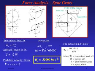
Some special cases you might see • Multiple links @ 1 joint At this joint, there are 2 unknown vector reactions, say F12 and F13 • Gears: The direction of the force between the gears is known (along the common normal), with the magnitude unknown
Special cases (cont.) • Hydraulic Cylinder: • Model as 2 rigid bodies, to result in an a fluid pressure force, a normal-wall force, and a wall torque • Model as a two force member, then there is one unknown, the force in the member (* preferred)
Force Analysis using the method of Virtual Work • If a rigid body is in equilibrium under the action of external forces, the total work done by these forces is zero for a small displacement of the body. • Work: • With F, x, T, q, vectors and W a scalar. • To indicate that we are dealing with infinitesimal displacements (virtual displacements), use the notation: • Now apply the virtual work definition:
Virtual Work (cont.) • If we divide the virtual work by a small time step, we get: • These are all external torques and forces on the body, and include inertial forces and gravity. Rewrite, to clearly show this as: With:
Virtual Work (cont.) • Notes • Solve the driving force of a single dof system with a single scalar equation • Internal forces (ex. Bearing reactions) cannot be solved with this technique.
Virtual Work: Example 1 (cont.)Given information: • Links 2 & 4 have mass • m2 = 10 kg, I2 = 1 kgm^2 • m4 = 100 kg I4 = 10 kgm^2 • Consider the cylinder, 5 as a 2 FM. Given the following motion information, find the input cylinder force and the bearing reactions at points O2 and O5. • Motion info: • w2=1, a2=1 rad/s^2, w4=1, a4=1 rad/s^2 • Vg2=-1i+0j m/s Vg4=-1i+1j m/s • Ag2=-1i-1j m/s^2 Ag4=-2i+0j m/s^2 • Vp=2j, V5=1i+1j • Force on bucket: • P = 100N