Error Force Analysis
Error Force Analysis. Error Force Analysis Detail.

Error Force Analysis
E N D
Presentation Transcript
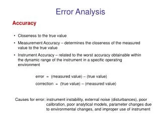
Error Force Analysis Detail • The error forces include V, M and (maybe) Fz. There will also be a shear and moment in the orthogonal plane and a torque or twist of the connecting rod. This happens everywhere that something touches the glass. All error forces at every location needs to be conservatively estimated and considered. • I usually consider position error of the puck/rod as a contributor to M, the moment, so I don’t book this separately. • I apply error forces at the support locations and calculate the appropriate surface distortion statistics (nm-rms surface). FEA codes require that the mirror rigid body motions be constrained so I use the kinematic constraint locations (if possible). V M Fz
Comments on Error Force Cases • Error forces are largely dictated by the installation tolerances. I always start loose and tighten as required so its convenient to make the FEA runs for error forces with unit loads and then scale the results (the surface statistics) later (it’s a linear analysis). • Reacting on the kinematic supports is conservative. I often need a more realistic reaction support for axial error loads when there are many more than three axial force reaction points. • Error forces in the z direction (surface normal) are much more damaging than others.
Sampling Error Forces • We have six axial rods. The rms surface distortion from a radial error force at any of these rods will be the same. • Instead of calculating the effect of an error force at each rod, sample one and RSS it into the overall result six times. • In deciding which location to sample pick the ones furthest from the reaction points (generally the kinematic constraints in the analysis).
Whiffle tree system error forces • It works out best for me to apply a moment at the seesaw pivot instead of estimating the axial error forces that result. These axial error forces are not statistically independent so this gets messy when you get up to an 18 point whiffle tree.
Systematic Distributions of Error Force • This is common. Test results are usually dominated by astigmatism but an error analysis assuming independent errors usually doesn’t predict much astigmatism. • Sources of systematic errors are thermal expansion of the cell and position error of the mirror relative to the cell. • If these don’t do it there’s a significant risk of getting an astigmatic distribution of error force out of a random distribution of axial error forces. The magnitude you can expect 32% of the time (1 sigma) runs at about Fzerr*sqrt(N/2) (I use base my estimates on 100 trials of random axial error force distributions and calculate the low order shape coefficients for each one). The mean of the coefficient is near zero but the standard deviations are as cited above. • I haven’t found it necessary to look for low order distributions of anything other than Fz.