Cooling Pipe Thermal Analysis for Manufacturing Tolerance Forces
Analyzing thermal and manufacturing forces on cooling pipes to determine disc deflections, stress in glue joints, with detailed examinations on manufacturing tolerances and different analyses for safe design.

Cooling Pipe Thermal Analysis for Manufacturing Tolerance Forces
E N D
Presentation Transcript
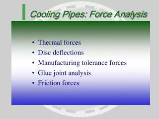
Cooling Pipes: Force Analysis • Thermal forces • Disc deflections • Manufacturing tolerance forces • Glue joint analysis • Friction forces
Thermal forces Temperature decrease 40 K
Thermal Deflections • Maximum deflection of the disc is 31 m • Thermal deflection of the cooling pipe between two cooling blocks if one end would be free: L = L · · T = 65 · 15 ·10-6 · 40 = 39 m • A manufacturing tolerance of this value would result in the same forces
Manufacturing tolerance • Analysis of pieces of cooling pipe between two adjacent blocks. One end gets a prescribed deflection, other end: • all six DOFs fixed • all DOFs fixed except one rotational DOF • Random effect, the average disc deflection is zero, deflections because of standard deviation • Stresses in the glue layer between insert and disc surface
Manufacturing tolerance forces One end displaced 0.1 mm in tangential direction
Actual situation • Holes in cooling blocks have diameter 2.2 mm, screws to attach cooling blocks to inserts are M1.6 • This means that the clearance between screw and hole is between 0 and 0.6 mm • Below this tolerance, the rotation can be set free. In a worst case situation the rotation has to be fixed if the manufacturing tolerance > 0.3 mm 2.2 1.6
Forces (Highest forces and torques occur at the inserts of the secondary middle cooling blocks)
Disc Deflection • Mean total force = 0, because of the random direction of the manufacturing tolerances, assume a normal distribution of the forces • Standard Deviation of the total tangential force total= F · n • Per insert: 4.2 · total /n = 4.2F/n (at Z = 4.2, the chance of exceeding this value is 0.1% in 18 discs) • Take mean tangential force of the secondary cooling blocks and the number n as the overall amount of secondary cooling blocks
Disc Deflection Same deflection as thermal deflection (31.2 m) will be reached at a manufacturing tolerance of 130 m Maximum deflection of disc (200 m) will be reached at a manufacturing tolerance of about 400 m
Analytical glue joint analysis Force glue glue with Filling in all properties: max = 0.4 MPa (with 0.5 mm manufacturing tolerance)
glue Analytical glue joint analysis Torque with Filling in all properties: max = 5.7 MPa (with 0.5 mm manufacturing tolerance)
Considerations • The calculated values for the shear stress are heavily depending on the boundaries of the glue joint • By making a well-finished glue joint, stresses can be brought down • Tests have to be done on the glue joint to get a good feeling of the glue strength
Numerical glue joint analysis 19.8 MPa
Numerical glue joint analysis 8.9 MPa
Numerical glue joint analysis 11.3 MPa
Prestressed screws • Cooling blocks are attached to insert with M1.6 • Max. prestressing force Fs = max · A • If max = 150 MPa and A = 1.27 mm², then Fs = 191 N per screw • Friction force Ff = 2·Fs· = 2·191·0.1 = 38.2 N • If manufacturing tolerance is 0.4 mm, then the force and the torque together give a force of 31.6 + 147/22.8 = 38.0 N
Concluding remarks • Keeping the manufacturing tolerance at 0.3 mm will be safe because of the low forces and zero moments • If 0.3 mm cannot be reached, 0.4 mm is the absolute maximum with respect to disc deflections • Glue joint analyses give very different results, because of the uncertatinties of the boundary geometry • 0.4 mm is a limit if there wouldn’t be a positioning pin between cooling block and insert; the positioning pin can take a lot of the friction force away