Force Analysis – Spur Gears
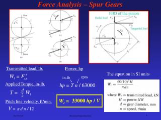
Transmitted load, lb. Power, hp. The equation in SI units. W t = F t. rpm. in-lb. 32. Applied Torque, in-lb. hp = T n / 63000. d. W t. T =. 2. 33000 hp / V. W t =. Pitch line velocity, ft/min. V = d n / 12. Force Analysis – Spur Gears. φ n = normal pressure angle.

Force Analysis – Spur Gears
E N D
Presentation Transcript
Transmitted load, lb. Power, hp The equation in SI units Wt = F t rpm in-lb 32 Applied Torque, in-lb. hp = Tn / 63000 d Wt T = 2 33000 hp/ V Wt = Pitch line velocity, ft/min. V = d n / 12 Force Analysis – Spur Gears Mechanical Engineering Dept.
φn= normal pressure angle φt= tangential pressure angle ψ = helix angle tanφn = tan φt cos ψ Wr = W sinφn Wt = W cosφn cos ψ Wa = W cosφn sin ψ Where W = total force Wr = radial component Wt = tangential component (transmitted load) Wa = axial component (thrust load) t= pressure angle (20o or 25o) Wr = Wt tanφt = helix angle (10, 20, 30, or 40o) Wa = Wt tanψ Force Analysis – Helical Gears Mechanical Engineering Dept.
Force Analysis – Bevel Gears = Pressure angle (20o) Mechanical Engineering Dept.
considering friction Relations between forces acting on the worm and the gear Force Analysis – Worm Gear Sets Three orthogonal components of W without considering friction Mechanical Engineering Dept.
Efficiency of worm gear sets (pressure angle) = 20o, 25o, 30o (max. pressure angle) = 25o, 35o, 45o Force Analysis – Worm Gear Sets Two useful relations, friction force and transmitted loads. Mechanical Engineering Dept.
Using similar triangles, Bending stress is maximum at the root of the tooth, Substituting for x and introducing p (circular pitch), The form factor y is called Lewis form factor. Substituting P = / p and Y = y Lewis’ equation, where Stress Analysis – Spur Gears Bending Strength Lewis’ equation (1892 Wilfred Lewis, Philadelphia Engineers Club) W t F Mechanical Engineering Dept.
Lewis’ equation, where Modification of Lewis’ Equation Assumptions made in deriving Lewis’ equation • The load is applied to the tip of a single tooth. • The radial component of the load, Wr , is negligible. • The load is distributed uniformly across the full face width. • Stress concentration in the tooth fillet is negligible. Mechanical Engineering Dept.
Modification of Lewis’ Equation Modifications according to AGMA standards (American Gear Manufacturers Association) Lewis’ equation W t tangential transmitted load Ka application factor KV dynamic factor KS size factor KI Idler factor (use 1.42 if designing an idler gear) Pd transverse diameteral pitch F face width of the narrower member Km load-distribution factor KB rim-thickness factor J geometry factor for bending strength which includes root fillet stress concentration factor Kf Mechanical Engineering Dept.
Geometry factor J Bending Stress Modifying Factors Mechanical Engineering Dept.
Application factor, Ka Bending Stress Modifying Factors Dynamic factor Kv Mechanical Engineering Dept.
Rim thickness factor KB Load Distribution factor Km Backup ratio Km = 1.6 may be used as a conservative value for face width less than 2 in. KB = -2mB + 3.4 0.5 mB 1.2 KB = 1.0 mB 1.2 Size factor Ks Bending Stress Modifying Factors AGMA has not established standards for size factor and recommends that Ks be set to 1. Mechanical Engineering Dept.
Reliability factor KR Temperature factor KT AGMA recommends using temperature factor of 1 for operating temperatures up to 250 oF. Consult the standards for higher temp. AGMA Bending Strength Equation Allowable Stress Sfb’ is the allowable fatigue bending stress, psi KLis life factor KT is the temperature factor KR is the reliability factor Mechanical Engineering Dept.
AGMA Bending Strength Equation Stress cycle factor KL Mechanical Engineering Dept.
AGMA Bending-Fatigue Strength, Sfb’ Mechanical Engineering Dept.
Initial scoring on 4340 steel helical gear Moderate scoring on a 3310 steel spur gear. Surface Strength Analysis The basic surface deterioration Scoring If the surface asperity welding and tearing cause a transfer of metal from one surface to the other, the resulting surface damage is called scoring. If the local welding of asperities becomes so extensive that the surfaces no longer slide on each other, the resulting failure is called seizure. Mechanical Engineering Dept.
Corrosion wear A type of surface deterioration that is caused by chemical reaction of lubricant, or of contaminants such as water or acids, with gear tooth surface. Surface Strength Analysis Abrasive wear Abrasive wear is a surface damage caused by the presence of abrasive particles in the lubricant. Large particles tend to scratch and gouge the surface, where small (dust like) particles polish the tooth surface to a mirror finish. Scoring, abrasive wear and corrosion wear are due to the failure of lubrication system. Mechanical Engineering Dept.
Surface Strength Analysis Surface Fatigue Failure, due to repeated contact load Proper lubricating system can minimize the surface damage due to wear and corrosion. But, surface fatigue can occur even with proper lubrication and it’s the most common mode of gear failure and is characterized by pitting and spalling of the tooth surface. The damage is caused by repeated contact stresses. Mechanical Engineering Dept.
Geometry factor cost sint mG mN = 1 for spur gears external gears 2mN mG + 1 mG= speed ratio = NG / NP I = cost sint mG internal gears 2mN mG - 1 AGMA Surface Stress Equation Cp elastic coefficient, (lb/in2)0.5 Wt transmitted tangential load Ca overload factor (same as Ka) Cv dynamic factor (same as Kv) Cs size factor (same as Ks) Cm load-distribution factor (same as Km) Cf surface condition factor d pitch diameter of the pinion F face width of the narrowest member I geometry factor Mechanical Engineering Dept.
Surface finish factor Cf AGMA recommends using surface finish factor of 1 for gears made of conventional methods. AGMA Surface Stress Equation AGMA Elastic coefficient CP Mechanical Engineering Dept.
Hardness ratio factor, CH CH should only be used for the gear design, for pinion design set CH equal to 1.0. AGMA Surface Strength Equation Sfc’ is the allowable contact stress, psi CLis the surface-life factor CT is the temperature factor (same as KT) CR is the reliability factor (same as KR) CH is the hardness ratio factor Mechanical Engineering Dept.
AGMA Surface Strength Equation Pitting resistance stress cycle factor ZN Mechanical Engineering Dept.
AGMA Surface Strength Equation AGMA allowable surface fatigue strength Mechanical Engineering Dept.
Outcome is Diameter and material AGMA Spur Gear Design Equations Surface strength design equation, Stress = strength Design steps • Calculate the transmitted load • Select material, start with grade 1 with low hardness. • Select standard full depth gears with pressure angle of 20o or 25o. • Choose a face width, ½ dP≤F≤dP • Decide on: load type (uniform, non-uniform), mounting accuracy, # of cycles to failure, gear quality and reliability. • Solve the design equation for the diameter. • Or, select diameter and solve for material. Mechanical Engineering Dept.
Outcome is Diametral pitch, P AGMA Spur Gear Design Equations Bending strength design equation Design steps • Assume a value for J (geometry factor), .35 to .45 • Solve the design equation to obtain the diametral pitch, Pd • Calculate the number of teeth for pinion and gear, determine the actual J and check against the assumed one, iterate if needed. • The number of teeth on the pinion should be over 18 to avoid interference. • For power transmission, 2 < Pd (diametral pitch) < 16 • Iterate until optimum design is achieved. Mechanical Engineering Dept.
Selections and assumptions • Standard full depth gears with pressure angle, φ = 20o, will be used. KR = CR= 1 Select 99% reliability • Assume uniform load Ka= 1 Design for 107 life cycle KL = CL= 1 Design a pair of spur gears to transfer power from a 25 hp motor to a fan. The motor turns at 1000 rpm and the desired fan speed is 500 rpm. Specify the material, diameter, and number of teeth for both gears. Design Example • Assume good quality gear with, Qv= 10, will be used. • Select face width F = dP (pinion diameter) , dP/2 ≤ F ≤ dP • Assume operating temp. less than 250o (KT=CT = 1), new gear (Cf = 1), and a small size gear (Ks=Cs = 1). Mechanical Engineering Dept.
From assumptions and selections list; Select material: use A-3 steel (hardness HB = 300), surface strength range from 120,000 to 135,000 psi. Use Sc = 125,000 psi in calculation. , Ca= 1 CR = 1 CL = 1 Cs = 1 Cf = 1 CH = 1 (pinion) , , , , , Look up CP (elastic coefficient) = 2300 cost sint mG = 0.107 I = 2mN mG + 1 φt = 20o mN = 1 for spur gears , mG= speed ratio = ωP / ωG = 1000/500 = 2 Surface failure Design Example Mechanical Engineering Dept.
Transmitted load WtV / 33000 hp = Wt = (1.26 x 10⁵) hp/ dPωP dP = 2.6 inch Design Example Pitch line velocity, ft/min. Wt = (1.26 x 10⁵) 25/ dP1000 V = π d ω / 12 Wt = 3150/ dP Assume dynamic factor C v = .9 and load distribution factor Cm = 1.6 Both assumptions have to be checked later. 2300[(3150/dP)(1/.9)(1.6)(1/.107)(1/dp)2]1/2 = 125,000 Mechanical Engineering Dept.
Check assumptions for Cv and Cm Cm = 1.61 (1.6 was assumed) F = dP = 2.6 Cv = .9 (.9 was assumed) Qv = 10 Select dP = 2.75 and A-3 steel as the material Design Example V = (πdPωP)/12 = π x2.6 x 1000/12 V = 680 ft/min With these corrections, dP = 2.6 Mechanical Engineering Dept.
Wt = (33000) hp/ V Wt = (33000) 25/ 680 Wt = 1213 lb P = 18.3 1213(1/.9)(P /2.75)(1.6)(1/.4) = 36,000 Design Example Bending failure For A-3 material, St = 36,000 – 47,000 psi Use 36,000 psi in calculation Assume J = .4, check later For power transmission, 2 ≤ P ≤ 16, so select P = 16 Mechanical Engineering Dept.
Spur gears specifications Material: A-3 steel Diametral pitch: P = 16 Diameter: 2.75 (pinion), 5.5 inch (gear) Number of teeth: 44 (pinion), 88 (gear) Face width: F = 2.75 inch Design Example Check assumption for J NP = PdP = 16 x 2.75 = 44 NG = PdG = 16 x (2.75x2) = 88 J = .43 P = 19.7 So P = 16 is valid Mechanical Engineering Dept.