Force Analysis
Unit 1<br>Engine force analysis


Force Analysis
E N D
Presentation Transcript
ME8594-DYNAMICS OF MACHINES UNIT -1
UNIT IFORCE ANALYSIS - 12 • Dynamic force analysis – Inertia force and Inertia torque– D Alembert’s principle –Dynamic Analysisin reciprocating engines – Gas forces – Inertia effect of connecting rod– Bearing loads – Crank shaft torque – Turning moment diagrams –Fly Wheels – Flywheels of punching presses- Dynamics of Cam- follower mechanism. • Introduction If the acceleration of moving links in a mechanism is running with considerable amount of linear and/or angular accelerations, inertia forces are generated and these inertia forces also must be overcome by the driving motor as an addition to the forces exerted by the external load or work the mechanismdoes.
Newton's Law • Newton’s Law: First Law Everybody will persist in its state of rest or of uniform motion (constant velocity) in a straight line unless it is compelled to change that state by forces impressed on it. This means that in the absence of a non-zero net force, the center of mass of a body either is at rest or moves at a constantvelocity. • Second Law A body of mass m subject to a force F undergoes an acceleration a that has the same direction as the force and a magnitude that is directly proportional to the force and inverselyproportional to the mass, i.e., F = ma. Alternatively, the total force applied on a body is equal to the time derivative of linear momentum of the body. • Third Law The mutual forces of action and reaction between two bodies are equal, opposite and collinear. This means that whenever a first body exerts a force F on a second body, the second body exerts a force −F on the first body. F and −F are equal in magnitude and opposite in direction. This law is sometimes referred to as the action-reaction law, with F called the "action" and −F the"reaction"
Typesof forceAnalysis • Equilibrium of members with twoforces • Equilibrium of members with threeforces • Equilibrium of members with two forces andtorque • Equilibrium of members with twocouples. • Equilibrium of members with fourforces • https://www.youtube.com/watch?v=D-YzoxtFBHs
Principle of Super Position • Sometimes the number of external forces and inertial forces acting on a mechanism are too much for graphical solution. In this case we apply the method of superposition. Using superposition the entire system is broken up into (n) problems, where n is the number of forces, by considering the external and inertial forces of each link individually. Response of a linear system to several forces acting simultaneously is equal to the sum of responses of the system to the forces individually. This approach is useful because it can be performed bygraphically. • https://www.youtube.com/watch?v=Fri3H_YcskI
D’AlembertsPrinciple • D'Alembert's principle, also known as the Lagrange–d'Alembertprinciple, is a statement of the fundamental classical laws of motion. It is named after its discoverer, the French physicist and mathematician Jean le Rondd'Alembert. The principle states that the sum of the differences between the forces acting on a system and the time derivatives of the momenta of the system itself along any virtual displacement consistent with the constraints of the system iszero • https://www.youtube.com/watch?v=nukQw1wavl4&list=PLdLe0dTcWW-t1rz5BDBzZVv-wHy2MabGK&index=1
D’Alembert’sPrincipal • D’Alembert’s principles states that the inertia force and torques, and the external forces and torques, acting on a body together result in statically equilibrium. • https://www.youtube.com/watch?v=jvBas8yUgNI
Dynamic Analysis of Four bar Mechanism . • A four-bar linkage or simply a 4-bar or four-bar is the simplest movable linkage. It consists of four rigid bodies (called bars or links), each attached to two others by single joints or pivots to form closed loop. Four-bars are simple mechanisms common in mechanical engineering machine design and fall under the study of kinematics • https://www.youtube.com/watch?v=j9Ztjs1tsi8&list=PLdLe0dTcWW-t1rz5BDBzZVv-wHy2MabGK&index=2
Dynamic Analysis of Four bar Mechanism • Dynamic Analysis of Reciprocating engines. • Inertia force and torque analysis by neglecting weight of connecting rod. • Velocity and acceleration ofpiston. • Angular velocity and Angular acceleration of connecting rod • Force and Torque Analysis in reciprocating engine neglecting the weight of connecting rod • Equivalent DynamicalSystem • Determination of two masses of equivalent dynamicalsystem
Dynamic Analysis of Four bar Mechanism https://www.youtube.com/watch?v=mSP1C5bmPj8
SESSION OBJECTIVES • Slider-crank mechanism • Displacement, velocity and acceleration of a slider in slider-crank mechanism. • Forces on an engine
Slider-Crank mechanism Inner-Dead center Outer-Dead center
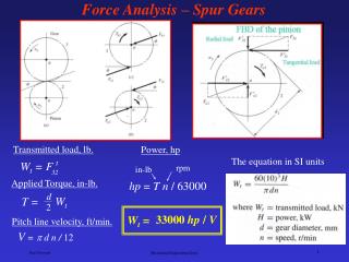
OQ = rcosq CQ = rsinq PQ = l cos f CQ= lsinf
ENGINE FORCE ANALYSIS • Newton’s law of motion: • First law of motion: • Everybody continues in its states of it rest or of uniform motion in a straight line unless an external resultant forces acts on it. • Thus, the Newton’s law helps us to define a force.
Second law of motion • The rate of change of momentum of a body is directly proportional to the force acting on it and takes place in the direction of force. • F =d dt (mv) = mdv dt Where, F=m.a F= Force acting on the particle m=Mass of the particle v= Velocity of the particle a=Acceleration of the particle
Third law of motion • To every action there is an equal and opposite reaction. • It means that the force of action and reaction between two bodies are equal in magnitude but opposite in direction • https://www.youtube.com/watch?v=_sr3hBxu614
Inertia Force • Inertia force = - External (or accelerating) force= -m.a Inertia Torque: • Torque, 𝑇∞ 𝑑 𝑑𝑡 (𝐼.𝜔) • Since I is constant, there fore 𝑇 = 𝐼 𝑑𝜔 𝑑𝑡 = 𝐼.𝛼 Where, • I= Mass moment of inertia of the body • 𝜔=Angular velocity of the body • 𝛼= Angular acceleration of the body • T= External (or accelerating) torque • https://www.youtube.com/watch?v=-Fz3LzbzKrQ
Free Body Diagram • A free body diagram is a pictorial representation often used by physicists and engineers to analyze the forces acting on a body of interest. A free body diagram shows all forces of all types acting on this body. Drawing such a diagram can aid in solving for the unknown forces or the equations of motion of the body. Creating a free body diagram can make it easier to understand the forces, and torques or moments, in relation to one another and suggest the proper concepts to apply in order to find the solution to a problem. The diagrams are also used as a conceptual device to help identify the internal forces—for example, shear forces and bending moments in beams—which are developed within structures.
Velocity and Acceleration of the Reciprocating Parts in Engines • The velocity and acceleration of the reciprocating parts of the steam engine or internal combustion engine (briefly called as I.C. engine) may be determined by graphical method or analytical method. • The velocity and acceleration, by graphical method, may be determined by one of the following constructions: • 1. Klien’s construction, • 2. Ritterhaus’s construction, • 3. Bennett’s construction. • We shall now discuss these constructions, in detail, in the following pages.
Approximate analytical method for velocity and acceleration of the piston • Consider the motion of a crank and connecting rod of a reciprocating steam engine as shown in Figure Let OC be the crank and PC the connecting rod. Let the crank rotates with angular velocity of ω rad/s and the crank turns through an angle θ from the inner dead centre (briefly written as I.D.C). Let x be the displacement of a reciprocating body P from I.D.C. after timetseconds, during which the crank has turned through an angle θ.
Approximate analytical method for velocity and acceleration of the piston • https://www.youtube.com/watch?v=RsuGFDcoB2Y&list=PLdLe0dTcWW-t1rz5BDBzZVv-wHy2MabGK&index=3
Approximate analytical method for velocity and acceleration of the piston • Motion of a crank and connecting rod of a reciprocating steam engine. Let l = Length of connecting rod between the centres, r = Radius of crank or crank pin circle, φ = Inclination of connecting rod to the line of stroke PO, and n = Ratio of length of connecting rod to the radius of crank = l/r.
Approximate analytical method for velocity and acceleration of the pistonVelocity of the pistonFrom the figure
Angular velocity and acceleration of the connecting rod • Consider the motion of a connecting rod and a crank as shown in Fig. 15.7.From the geometry of the figure, we find that CQ = l sinφ=r sinθ
DYNAMIC FORCEANALYSISVelocity and Acceleration of Reciprocating Part • https://www.youtube.com/watch?v=RsuGFDcoB2Y&list=PLdLe0dTcWW-t1rz5BDBzZVv-wHy2MabGK&index=3
DYNAMIC FORCEANALYSIS • Displacement of piston (x) = r[(1-cos θ)+sin2θ /2n] • Velocity of Piston (Vp) = • Acceleration of Piston (Ap) = • Angular velocity of connecting Rod (ωc ) = • Angular acceleration of connecting Rod (Ac) = - ω2 Sinθ/n
Session objectives • Motion analysis of slider Crank mechanism • How to calculate the displacement, velocity and acceleration. • Forces acting in a slider Crank mechanism • Torque in an engine
Slider Crank mechanism- Analysis • Displacement of piston,x = • Velocity of piston, v = • Acceleration of piston, a =
Motion Analysis Problem • The crank and connecting rod of a steam engine are 0.3 m and 1.5 m in length. The crank rotates at 180 r.p.m. Clockwise. Determine the velocity and acceleration of the piston when the crank is at 40 degrees from the inner dead centre position. Also determine the Position of the crank for zero acceleration of the piston. Given r=0.3 m, l = 1.5 m N = 180 rpm q = 40 Deg.
To find • v • a • q = ? When a=0 • Solution • r=0.3 m, l = 1.5 m, N = 180 rpm, q = 40 Deg. • ω= π* N / 60 = π* 180/60 = 18.85 rad/s • Velocity of piston:
Solution R=0.3 m, l = 1.5 m, N = 180 rpm, q = 40 Deg. • = π* N / 60 = π* 180/60 = 18.85 rad/s Acceleration of piston:
Angular displacement: Formulae
Problems on Approximate analytical method for velocity and acceleration of the piston • .In a slider crank mechanism, the length of the crank and connecting rod are 150 mm and 600 mm respectively. The crank position is 60° from inner dead centre. The crank shaft speed is 450 r.p.m. (clockwise). Using analytical method, determine: 1. Velocity and acceleration of the slider, and 2. Angular velocity and angular acceleration of the connecting rod.
Given : r = 150 mm = 0.15 m ; l = 600 mm = 0.6 m ; θ = 60°; N = 400 r.p.m or ω=π× 450/60 = 47.13 rad/sTo Find: Velocity and acceleration of the slider and Angular Velocity and Angular Acceleration of the connecting rod Solution: Using Formula: • Velocity of Piston (Vp) = • Acceleration of Piston (Ap) =
Solution for Velocity and acceleration of the slider We know that ratio of the length of connecting rod and crank, n= l/r= 0.6 / 0.15 = 4
Solution for Angular Velocity and Angular Acceleration of the connecting rod