Download

1 / 13
130 likes | 254 Views
This update discusses the advancements in the MICE tracker readout system, focusing on the Analog Front End II (AFE-IIt) boards designed for increased data throughput. These boards facilitate the digitization of analog signals from the VLPC cassettes, enabling optimized data rates for tracking muons at the MICE experiment. Key components like TriP-t, AFPGA, and DFPGA are detailed, highlighting their roles in enhancing performance and data processing. The anticipated schedule outlines firmware development and testing phases to ensure compatibility and functionality.

E N D
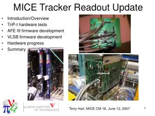
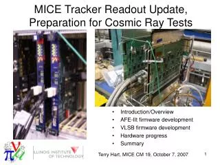
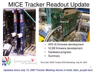
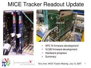
MICE AFE-IIt Update Increased Data Readout Rate VLSB Development - 16 AFE-IIt boards - 8 Visible Light Photon Counter (VLPC) cassettes - 4 cryostats Terry Hart, Terry Hart, NFMCC Friday Meeting, November 10, 2006
MICE Tracker Readout Overview • Analog Front End II t (AFE-IIt) boards: • Developed for D0 tracker upgrade • Will be used for MICE tracker readout • Inputs: Analog charge signals from 512 channels • Outputs: Digital hit pattern, charge amplitudes, time amplitudes
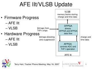
AFE-IIt Component Overview TriP-t (Trigger and Pipeline with time) • 32 channel, fully custom, mixed signal ASIC • Receives amplified signals from VLPCs • Main functions • Provide prompt discriminator bitmap to digital FPGA (DFPGA) • Provide, on demand, analog charge and time information stored in pipeline from earlier event, to ADCs DFPGA AFPGA AFPGA ADC ADC ADC ADC TriP-t TriP-t TriP-t TriP-t Data from VLPCs ¼ of AFE-IIt board
AFE-IIt Component Overview ADC • Dual channel, 10-bit, 20 Msamples/sec • Digitizes analog charge and time signals from TriP-t chips upon receipt of trigger • Sends digitized data to AFPGAs DFPGA AFPGA AFPGA ADC ADC ADC ADC TriP-t TriP-t TriP-t TriP-t ¼ of AFE-IIt board
AFE-IIt Component Overview AFPGA (Analog FPGA) • Controls operation of ADCs and TriP-t chips • Will receive discriminator bitmap from DFPGA and send processed data to DFPGA • Part of MICE firmware development • Necessary for increased data throughput DFPGA AFPGA AFPGA ADC ADC ADC ADC TriP-t TriP-t TriP-t TriP-t ¼ of AFE-IIt board
AFE-IIt Component Overview DFPGA (Digital FPGA) • Will send discriminator bitmap to AFPGA • After AFPGA processes data, DFPGA will • Receive data from AFPGA • Send data to VLSB banks along LVDS links • Part of MICE firmware development • Necessary for increased data throughput Data to VLSB DFPGA AFPGA AFPGA ADC ADC ADC ADC TriP-t TriP-t TriP-t TriP-t ¼ of AFE-IIt board
MICE Tracker Readout Overview - Final data destination: VME LVDS Serdes Buffer (VLSB) banks via Low Voltage Differential Signaling (LDVS) links. - KEK test beam data readout to VLSB banks: One trigger at a time. - VLSB firmware needs to be modified for MICE. (~600 muon triggers per 1 ms wide spill)
MICE Requirements for Tracker Readout • Data Rate: MICE goal of reading out 600 muons every 1 ms spill. • D0 tracker readout optimized for TeVatron beam. • For MICE, current microcoding allows ~225 muons/ms. • Data Readout: MICE tracker data will be read out to VLSB banks. • D0 data read out to digital boards and SVX sequencers.
Data Rate through Zero-Suppression • D0 firmware uses 6 clock cycles for every AFE II t channel. • For channels above threshold, ~100 ns or about 6 clock cycles needed for digitization. • Reduce digitization time by using 1 or 2 clock cycles for channels below threshold. (1 TeVatron clock cycle = 1/53.104 MHz = 18.831 ns) Illustration of timing of 4 channels below threshold followed by 1 channel above threshold for compression scheme and nominal scheme.
Simulated MICE Tracker Data Readout Signals Channels 9, 17, 20, and 27 being digitized List of 4 channels above threshold
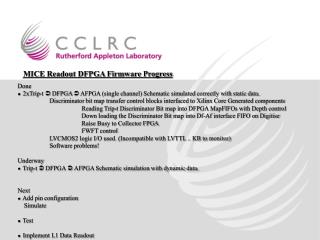
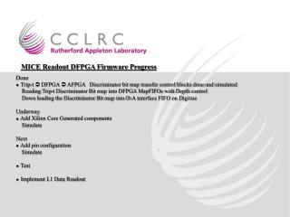
Data Rate • What's done: • Modified AFPGA firmware generating signals appropriate for data rate scheme. • Signals to ADCs • Signals to TriP-t chips • Signal simulations verifying that code logic is correct. • What needs to be done: • Firmware providing bitmap to the AFPGA to implement data rate scheme. • Verification of digitization with input signals. • Further modifications to make data readout compatible with ISIS beam.
Data Readout • What’s done: • Firmware written which • Transfers sequence of test data words into AFE-IIt RAM blocks • Read out test data from RAM blocks to VLSB banks via LVDS lines. • Programs VLSB to store data from multiple triggers before readout through VLSB register manipulation. • Tested VLSB hardware and verified that banks are storing and reading back data without corruption. • What needs to be done: • Work with VLSB experts to fix/modify VLSB firmware. • Add MICE-specific event triggering implementation • Add capability to trigger on any of 4 SERDES banks • Test this AFE-IIt readout to VLSB with LED/cryostat/VLPC system.
Anticipated Schedule • Now: AFE-IIt boards reserved for MICE • We have 8 AFE-IIt boards (4 LH and 4 RH). • Paul Rubinov, supervisor of the AFE-IIt testing, told me “MICE gets boards when MICE needs boards.” • Late November, early December: Firmware coding done • Late November: Firmware testing with input signals and AFE-IIt boards. • Late 2006, early 2007: Test AFE-IIt readout to VLSB with cryostat/LED/VLPCs.