Download
1 / 41
410 likes | 520 Views
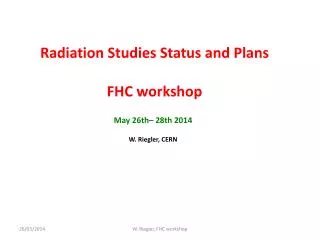
Radiation Studies Status and Plans FHC workshop. May 26th– 28th 2014 W. Riegler, CERN. Rough check on a few basic points. How do multiplicities , particle energy and radiation dose at a 100TeV FHC compare to 14 TeV HL-LHC ?

E N D
Radiation Studies Status and Plans FHC workshop May 26th– 28th 2014 W. Riegler, CERN W. Riegler, FHC workshop
Rough check on a fewbasicpoints How do multiplicities, particleenergyandradiation dose at a 100TeV FHC compareto 14 TeV HL-LHC ? Whatcouldweexpectfromsiliconsensors in 10-20 yearsfromnow ? Are thereissueswithveryshortbunchcrossingtimesof 5ns ? Will webeableto push thedatafrom an FHC detectorintothe online systems, withouttheneedfor a hardwaretriggerlevel? Whatarethenextstepsnecessaryforevaluationofradiationandshielding ? W. Riegler, FHC workshop
DetectorLayout Will useoneoftheconceptsfrom Daniel Fournier & Co W. Riegler, FHC workshop
Inelastic pp crossection 100TeV 14TeV Inelastic pp crossection, handextrapolationfromdataupto 7 TeV: ≈ 80mb at 14TeV ≈ 100mb at 100TeV 25% increase W. Riegler, FHC workshop
Multiplicities W. Riegler, FHC workshop
Multiplicities 100TeV Extrapolation forinelastic pp events 0.8xs0.1 Chargedparticlemultiplicityat 14TeV ≈ 5.4 100TeV ≈ 8 onlyabout 1.5 times larger 1.54-0.096 ln (s)+0.0155 ln2 (s) W. Riegler, FHC workshop
Average ParticleMomentum 14TeV 100TeV 0.413-0.0171 ln (s)+0.00143 ln2 (s) • Average pTapprox. 0.6GeV/c for 14 TeVand 0.8GeV/c at 100TeV • i.e. increaseof 33%. • Bending in radius in 4T field: • R[m] = 3.33 * pT[GeV/c] / B[T] = 3.33 * 0.8/4 = 0.67m • Average particle will curlwith 1.33m diameterinsidethe ID. W. Riegler, FHC workshop
Curling circleofaveragepTparticleat B=4T W. Riegler, FHC workshop
EnergyDeposit in Tracker Elements Momentum p forpTof 0.8GeV/c p[GeV/c] p=0.8*Cosh[η] Pseudorapidityη Pions are dominant particlespecies. Close to MIP. For Si, C i.e. detectormaterialslet‘sassume 1/ρ * dE/dx = 2MeV cm2/g W. Riegler, FHC workshop
Ionizing Dose Assuming N ionizingparticles per cm2 thereare N*A particlespassingthevolume. ΔE=N*A*ρ[g/cm3]*2 MeV[cm2/g]*d[cm] Δmass = ρ[g/cm3]*d[cm]*A[cm2] Dose = ΔE/Δmass = 3.2e-10*N[cm-2] Gray A d N W. Riegler, FHC workshop
Multiplicities η =-5 -3 3 5 In thepseudorapidityrangeofη ±3 (±5) themultiplictyvariesonlybyabout 10% (50%) BoostInvarianceof pp collisions. Assuming a constantvalueequaltothecentralonegives a slightlyconservative estimateoftheparticlemultiplicity in theentiretrackingrange. W. Riegler, FHC workshop
Fluenceand Dose fromprimarytracks ΔN η =0 w E.g. first Pixel Layer Δz Δθ s r θ η =∞ IP ΔA • Fluence = numberofparticlestraversing a detectorelementsweightedbythetracklength in the material. • The hadronfluence due toprimaryparticlesis just a functionofthedistancefromthebeamline. • Eqi-fluenceandequi-dose linesareparallelstothebeamline. W. Riegler, FHC workshop
Crosscheckwith original ATLAS ID TDR ChargedHadronFluence Constant in parallelstobeamline 1MeV-neq fluence, Constant in parallelstothebeamine. However, closetoabsorbers, manyneutronsescape – clearly different W. Riegler, FHC workshop
Fromchargedparticlefluenceto 1MeV neutronequivalentfluence Damagefunctionforcalculationof 1MeV n-equivalentfluencefortheprimaryhadrons in thelowGeVrangeiscloseto 1. Assumingnomagneticfieldandonlyprimarychargedhadronsfrom pp collisions, weexpectthattheionizing dose andthe 1 MeVneutronequivalentfluenceareonly a functionofthedistancefromthebeampipeandindependentofthedetectororientations, andgivenby N0 = dN/dηatmidrapidity Npp = numberof pp collisions W. Riegler, FHC workshop
Crosscheckwith ATLAS Phase II LOI 3000 fb-1 80mb inelastic pp crossection 2.4 * 1017events dN/dη = N0=5.4 at 14 TeV Pixel layer1 atr=3.7cm 1MeVneq Fluence = 2.4*1017*5.4/(2*π*3.72) = 1.5*1016 cm-2 Dose = 3.2x10-8*1.5*1016 = 4.8MGy W. Riegler, FHC workshop
Crosscheckwith ATLAS Phase II LOI excellentagreement off byfactor 4 at 30cm ATL-UPGRADE-PUB-2012-003 W. Riegler, FHC workshop
Crosscheckwith ATLAS Phase II LOI ATL-UPGRADE-PUB-2012-003 excellentagreement off byfactor 10 at 100cm W. Riegler, FHC workshop
Crosscheckwith ATLAS Phase II LOI Addingsome 1/rcomponent. 1/a= distancewheredirectandsecondaryparticlesare in same numbers. 1/a=6.7cm W. Riegler, FHC workshop
FHC 100TeV Average pile-up: ~140/xing Assume: Luminosity 5x1034 in 25ns or 5ns bunchspacing. Integrate 3000fb-1. W. Riegler, FHC workshop
FHC 100TeV veryuncertain quiteprecise • 3000 fb-1 • 100mb inelastic pp crossection • 3 * 1017events • dN/dη = N0 = 8 • Pixel layer1 atr=3.7cm • 1MeVneq Fluence = • 3*1017*8/(2*π*3.72) = • 2.8*1016 cm-2 • Dose = 3.2x10-8*2.8*1016 = • 9MGy • Integrating 3000fb-1 of pp collisionswith a FHC detector will result in 2x the HL-LHC fluenceand dose numbersforthefirstpixellayeratr=3.7cm. • For 10000fb-1 i.e. 10 ab-1thehadronfluenceiscloseto 1017cm-2 1/a=10cm 1MeV neqfluence (cm-2) 1014 3000 fb-1 onlyprimaries 1013 Radius (cm) 3000 fb-1 1/a=10cm Ionizing Dose (MGy) 50kGy onlyprimaries 2kGy W. Riegler, FHC workshop Radius (cm)
Conslusion 1/2 Assuming an integratedluminosityof 3000 fb-1 andthefirstpixellayeratr=3.7cm fromthebeampipethefluenceand dose for 14(100)TeVare 1.5(3)1016cm-2and 5(10)MGy i.e. thenumbersfor an FHC detectorareonlyabouttwicethe HL-LHC numbers (unlessoneputsthefirstpixelcloser). The fluenceand dose numbersfor a distanceof 2.5m fromthe IP for3000 fb-1 of 100TeV collisionsarebetween 1013and 1014 cm-2and 2-50 kGy. W. Riegler, FHC workshop
Detector Technologies Record fields Practical magnets Magnets between 1980 to 2000: factor 3 withdifficultprospects ... Transistor count & storagecapacity -- factor 2 everytwoyearssince 1960ies withgoodhopeforcontinuation ! Assumefactor 210 = 1024 from 2014 – 2034 W. Riegler, FHC workshop
Moore‘s Law http://www.livescience.com/23074-future-computers.html • Ifthedoublingofcomputing power everytwoyearscontinuesto hold, "thenby 2030 whatevertechnologywe'reusing will besufficientlysmallthatwecan fit all thecomputing power that's in a human braininto a physicalvolumethesizeof a brain," explained Peter Denning, distinguishedprofessorofcomputerscienceattheNavalPostgraduate School and an expert on innovation in computing. "Futuristsbelievethat'swhatyouneedforartificialintelligence. Atthatpoint, thecomputerstartsthinkingforitself.“ • Computers will anywaybythemselvesfigure out whatto do withthedataby 2035. • Magnet systemandshielding will beratherconventionalandcanbeworked out tosomedetailnow. • Fordetectortechnologyandcomputing power weareallowedtodream a bit. W. Riegler, FHC workshop
LHC to HL-HLC ATLAS/CMS plansfor L=5x1034 4 GHz Event Rate @ 40MHz 0.8 GHz Event rate @ 40MHz ÷ 40 ÷ 400 0.5-1 MHz Level-1 Rate 100kHz Level-1 ÷ 100 ÷ 1000 5-10kHz Rate to Tape 100Hz On tape Increase in computing power, accordingto Moores Law doublingevery 2 years, andrelatedincrease in storagecapacity, makesitpossible ! W. Riegler, FHC workshop
LHCb & ALICE in 2018 4 TByte/s into PC farm 1 TByte/s into PC farm 40 MHz 40 MHz 50 kHz Reconstruction + Compression 5-40 MHz 50 kHz (1.5 MB/event) 20 kHz (0.1 MB/event) Storage PEAK OUTPUT 75 GB/s 2 GB/s
ATLAS & CMS Triggered vs. Triggerless Architectures (2022) • 1 MHz (Triggered): • Network: • 1 MHz with ~5 MB: aggregate ~40 Tbps( 5 TByte/s) • Links: Event Builder-cDAQ: ~ 500 links of 100 Gbps • Switch: almost possible today, for 2022 no problem • HLT computing: • General purpose computing: 10(rate)x3(PU)x1.5(energy)x200kHS6 (CMS) • Factor ~50 wrt today maybe for ~same costs • Specialized computing (GPU or else): Possible • 40 MHz (Triggerless): • Network: • 40 MHz with ~5 MB: aggregate ~2000 Tbps( 200 TByte/s) • Event Builder Links: ~2,500 links of 400 Gbps • Switch: has to grow by factor ~25 in 10 years, difficult • Front End Electronics • Readout Cables: Copper Tracker! – Show Stopper • HLT computing: • General purpose computing: 400(rate) x3(PU)x1.5(energy)x200kHS6 (CMS) • Factor ~2000 wrt today, but too pessimistic since events easier to reject w/o L1 • This factor looks impossible with realistic budget • Specialized computing (GPU or …) • Could possibly provide this …
Trigger CMS assumes 5MByte/eventforthe Phase II upgrade detector i.e. for a levelledluminosityof 5x1034 . At 40MHz bunchcrossing rate thisresults in 200TByte/s intothe online systemfor a triggerlessreadout. For 2022 thisisconsideredtoodifficult. Assumingthatthe total track rate for 100TeV pp collisionsisonly a factor 2 larger, thereisverylittledoubtthatby 2035 and FHC detectorcanberead out in a triggerlessfashion. In 2035 notriggernecessary ! All datatothe online system, synchronousorasynchronous. W. Riegler, FHC workshop
ALICE 2018 upgrade, 20x20um monolithicpixels CERN-LHCC-2013-024 W. Riegler, FHC workshop
Technical design reportforthe upgrade ofthe ALICE innertrackingsystemCERN-LHCC-2013-024 • Standard processing, nobumpbonding (>>50% of Pixel detectorcost). Allowsimplementationofcomplexprocessingelectronicsinsidetheentirepixelarea. • Revolution ! W. Riegler, FHC workshop
Pixel Revolution Hybrid Monolythic • Dramaticdecrease in cost. • Verylow power consumption, possibly <100mW/cm2i.e. simple watercooling • Ultra low material budget<0.5% forinnerlayers, <1% forouterlayers. • Questionofspeedandradiationhardness: • Atpresent, • integration time of 4μs (noise, electrondiffusion) • radiationresistanceuptofew 1013neq. • Development (next 20 years) towards larger (full) depletion will improvespeedandradiationhardnesssignificantly. • Also – in caseonehas a fullpixeltrackeronecanuse 1 or 2 layerswith ‚fast‘ pixelsto do the BCID (25ns oreven 5ns) andthenmatchtheotherhits. • With a fullpixeltrackerof 20x20um pixelsonecanpileup a fair amountofeventsbeforeoccupancygetsto large !!! Technical design reportforthe upgrade ofthe ALICE innertrackingsystemCERN-LHCC-2013-024 W. Riegler, FHC workshop
Time stampingofchargedparticleswith a siliconsensor Time resolutionbelow 200ps – makes BCID feasibleevenfor 5ns FHC bunchcrossing. W. Riegler, FHC workshop
Tracker Area Trackercylindersfromη = 0 to 2 17 layersatradii 4+n*15cm (n=1 to 16) First at 4cm, last at 244cm, total area = 1600m2 First 4 layers ‚fast‘ pixelsfor BCID, 13 layers ‚slow e.g. 100ns‘ monolithicpixels (neq <1015cm-2) Includingforwardsdiscsaround 3000m2 = 6 times CMS = 300 times ALICE ALICE 10m2with 20x20um pixels = 25GPixels FHC Detector 3000m2with 20x20um pixels = 7500GPixel = 7.5TPixel W. Riegler, FHC workshop
Tracker Data Rates • Assumea fullpixeltracker: • L=5x1034at 100TeV 5x10⁹ pp collisions/second • dN/dη = 8 i.e. 80 tracksinsideη ±5 • Eachtrackcrosses 15 trackingstations • In eachstation 5 pixelsarefired. • Eachhitisencoded in 5 Bytes • Factor 5 forbackground + curling etc. • 750 TByte/secondinto online system • Not totallyinsane • (Fairly easy tosimulate) W. Riegler, FHC workshop
Itishighly probable thatby 2035 thereisnoneedfor a Hardware L1 trigger All dataarepushedinto a PC farm. • Itishighly probable thatmonolythicsiliconsensors will revolutionizeourfieldandarriveatradiationhardnessnumbersof 1015 cm-2neqormoreand ‚chargecollectiontimes‘ oflessthan 100ns. • Maybe also calorimetrycanbebased on Silicon. • Weshouldmakesurethatwe do not putconstraints on the FHC acceleratorpeople. Theyshouldprovidethemaximumenergyandmaximumluminosity – we will forsurebeabletomakebestuseof it. W. Riegler, FHC workshop
BEBC photopgraphs, untriggered ALEPH triggered, onlywirechamberreadout. ATLAS/CMSLHCb/ALICE complextrigger, Si, Larg, Wires, RPC, Crystals, Scintillator ... Onlyonepixelchip, fortrackingandcalorimetrywithtriggerelessreadoutto PCs ? W. Riegler, FHC workshop
Next Stepsfor Radiation Calculations W. Riegler, FHC workshop
Interaction Region and Final Focus Design R. Tomas • Proof of principle: • L* = 46m (goal >25m) • b*= 0.8m (goal <1.1m) • 1100m long (goal <1400m) Would like to be able to reduce beta-function further Hardware integration and constraints Technology choices to be made Shielding of magnets is critical So excellent start, but much more work to be done See R. Tomas in breakout session
2xL* = 92m = Distancebetweem Final Focussing Triplets D. Fournier ATLAS/CMS cavernlength: 62/53m ATLAS/CMS detectorlength: 22/42m W. Riegler, FHC workshop
2xL* = 92m = Distancebetweem Final Focussing Triplets • Place thetripletsat proper L* and ‚workintothecavern‘ fromtherewithshieldingsa‘la TAS/TAN, in orderto find a minumumlayoutthatprotectsthetriplet. • See whattheremaining beam backgroundfromtunneltocavern will be, given a minimumbeampipelayout. • Estimateactivationlevelstounderstandaccessrestrictions. • Due tothe large L* thereseemstobequitesomespaceavailable, so the TAS/TAN are not necessarilyhighlyintegratedwiththedetectors. • Identifypeoplewhocanrunthesesimulations. W. Riegler, FHC workshop