Download
1 / 31
310 likes | 338 Views
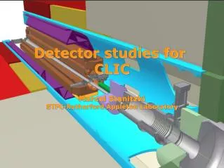
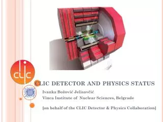
CLIC Detector studies status + plans. Contents: Introduction to CLIC accelerator 2004 CLIC Study group report: "Physics at the CLIC Multi-TeV Linear Collider“ CERN participation in Linear Collider R&D (EUDET, DevDet) ILC-CLIC collaboration. QUAD. QUAD. POWER EXTRACTION. STRUCTURE.

E N D
CLIC Detector studiesstatus + plans Contents: Introduction to CLIC accelerator 2004 CLIC Study group report: "Physics at the CLIC Multi-TeV Linear Collider“ CERN participation in Linear Collider R&D (EUDET, DevDet) ILC-CLIC collaboration Lucie Linssen, Krakow FCAL meeting 6/5/2008 slide 1
QUAD QUAD POWER EXTRACTION STRUCTURE ACCELERATING STRUCTURES BPM CLIC basic features CLIC TUNNEL CROSS-SECTION High acceleration gradient: > 100 MV/m • “Compact” collider – total length < 50 km at 3 TeV • Normal conducting acceleration structures at high frequency Two-Beam Acceleration Scheme • Cost effective, efficient • Simple tunnel, no active elements • Modular, easy energy upgrade in stages 4.5 m diameter Drive beam - 95 A, 240 ns from 2.4 GeV to 240 MeV 12 GHz – 64 MW Main beam – 1 A, 156 ns from 9 GeV to 1.5 TeV 100 MV/m Lucie Linssen, Krakow FCAL meeting 6/5/2008 slide 2
326 klystrons 33 MW, 139 ms 326 klystrons 33 MW, 139 ms combiner rings Circumferences delay loop 80.3 m CR1 160.6 m CR2 481.8 m drive beam accelerator 2.37 GeV, 1.0 GHz drive beam accelerator 2.37 GeV, 1.0 GHz CR1 CR1 1 km 1 km delay loop delay loop Drive Beam Generation Complex CR2 CR2 decelerator, 24 sectors of 868 m BDS 2.75 km BDS 2.75 km BC2 BC2 245m 245m IP1 e- main linac , 12 GHz, 100 MV/m, 21 km e+ main linac TA R=120m TA R=120m 48 km CLIC overall layout 3 TeV booster linac, 9 GeV, 2 GHz Main Beam Generation Complex BC1 e- injector 2.4 GeV e+ injector, 2.4 GeV e+ DR 365m e- DR 365m CLIC layout Lucie Linssen, Krakow FCAL meeting 6/5/2008 slide 3
CLIC main parameters http://clic-meeting.web.cern.ch/clic-meeting/clictable2007.html Lucie Linssen, Krakow FCAL meeting 6/5/2008 slide 4
e- e+ 3x more energy loss due to beamstrahlung at CLIC w.r.t. ILC unavoidable at Linear Colliders in general: small beam sizes -> large beamstrahlung Lucie Linssen, Krakow FCAL meeting 6/5/2008 slide 5 CLIcC luminosity spectrum
Time structure of the beam Train repetition rate 50 (100) Hz CLIC 1 train = 312 bunches 0.5 nsec apart ILC 5 Hz 1 train ~2820 bunches ~337 ns apart Experimenting at CLIC similar to the “NLC” Time stamping! Lucie Linssen, Krakow FCAL meeting 6/5/2008 slide 6
CLIC links, workshops and time-line CLIC website: http://clic-study.web.cern.ch/CLIC-Study/ CLIC07 workshop, October 2007 http://cern.ch/CLIC07Workshop CLIC08 workshop, October 14-17 2008 CLIC CDR foreseen for 2010 CLIC TDR foreseen for 2014 Lucie Linssen, Krakow FCAL meeting 6/5/2008 slide 7
Detector Specifications hep-ph/0412251 ; CERN-2004-005 CLIC Report 2004: Starting point: the TESLA TDR detector adapted to CLIC environment • - Detailed studies performed for • previous CLIC parameters • Update with new CLIC parameters • is underway • Greater need for time-stamping • of events • No significant physics difference • found previously between NLC and • TESLA at sub-TeV energies • None expected between old and • new multi-TeV parameters Lucie Linssen, Krakow FCAL meeting 6/5/2008 slide 8
CERN participation in LC: EUDET 2006-2009 • MICELEC: microelectronics user support • VALSIM: optimisation of hadronization process in GEANT4 • Magnet: magnetic field map of PCMAG magnet at DESY test beam • Timepix: development of pixel chip for TPC pixelised readout • TPC electronics: development of TPC pad readout (aiming for combined analog/digital readout fitting behind 14 mm2 pads) Lucie Linssen, Krakow FCAL meeting 6/5/2008 slide 9
INPUTS 5 versions 7 standard channels PCMAG field map campaign at DESY 2007 OUTPUTS Timepix chip TPC pad readout, programmable amplifier 130 nm technology Lucie Linssen, Krakow FCAL meeting 6/5/2008 slide 10
CERN contribution to LC tasks in FP7 proposal DevDet http://project-fp7-detectors.web.cern.ch/project-FP7-detectors/Default.htm • Test beam for combined linear collider slice tests (providing beam, large magnet, general infrastructures etc.) • Continued support for TPC electronics • Participation in Project office for linear collider detectors (engineering tools for project office; design support for test beam set-up) • Test-case of LC project tools on CLIC forward region example (together with DESY and ILC forward study teams) • Software tools (geometry and reconstruction tools) • Microelectronics user support Lucie Linssen, Krakow FCAL meeting 6/5/2008 slide 11
From: F. Richard, Sendai Lucie Linssen, Krakow FCAL meeting 6/5/2008 slide 14
ILC-CLIC working groups First working group meeting, 13/5/2008 Lucie Linssen, Krakow FCAL meeting 6/5/2008 slide 15
Topics for CLIC-ILC Detector R&D Summary: Detectors from meeting 8 Feb 08: 1) Define a CLIC detector concept at 3 TeV. (update of 2004 CLIC Study) based on ILC detector concepts. 2) Detector simulations - Simulation tools to be used by ILC and CLIC (WWS software panel) - Validation ILC detector options for CLIC at high energy, different time structure and different backgrounds - 1 TeV benchmark studies to provide overlap - compare performance using defined benchmark physics processes (e.g. WW/ZZ separation) Lucie Linssen, Krakow FCAL meeting 6/5/2008 slide 16
Continue Summary CLIC/ILC detector R&D, 8/2/’08 3)EUDET /DEVDET ( infrastructure for LC detector R&D, with associated non-EU groups) - microelectronic tools - 3D interconnect technologies (for integrated solid state detectors) - simulation and reconstruction tools - combined test with magnet and LC sub-detectors 4)TPC - TPC performance at high energies (>500 GeV). - TPC read out electronics 5)Calorimetry - Dual Readout Calorimetry (feasible at LC?) 6) General - increased CLIC participation in future ECFA workshops (2008 Warsaw) on LC detectors Lucie Linssen, Krakow FCAL meeting 6/5/2008 slide 17
Machine Detector Interface (from summary 8/2/2008) • General layout and integration • Common meeting/review required • Common engineering tools for detector design in preparation (DESY, CERN, IN2P3, FP7) • Background and luminosity studies • Strengthen support • Masking system • Constraints on vertex detector • Detector field • Need a field for CLIC • Magnet design • Common simulation tools for detector studies • Need to review what is available • Low angle calorimeters • Beam pipe design (LHC) • Vacuum etc. (LHC) Lucie Linssen, Krakow FCAL meeting 6/5/2008 slide 18
Background and Luminosity Studies (from summary 8/2/2008) • Common simulation tools • BDSIM () • Integration into GEANT? • FLUKA (CERN) • Halo and tail generation (CERN) • Common formats etc • Study of machine induced background • In particular, neutrons, muons and synchrotron radiation • Mitigation strategies • e.g. tunnel fillers against muons • Study of beam-beam background and luminosity spectrum Lucie Linssen, Krakow FCAL meeting 6/5/2008 slide 19
Support, Stabilization and Alignment (from summary 8/2/2008) • LAPP, Oxford, CERN, FP7, BNL, SLAC, … • Other please join • Low-noise design • Noise level measurements (DESY, CERN) • Among others, measurements at LHC • Component design • Mechanical design of quadrupole support • Final quadrupole design • Stabilization feedback design • Sensors • Actuators • Interferometers Lucie Linssen, Krakow FCAL meeting 6/5/2008 slide 20
Experimental Area Integration (from summary 8/2/2008) • Common definitions • Infra-structure • Work is quite generic • No large differences expected for CLIC detector to some ILC detector • Collaboration has started • LHC expertise • Push-pull • Is an option for both projects • A collaboration has started • Brings ILC/CLIC/LHC expertise • Crossing angle • Investigate requirements • Then study benefits to find a common crossing angle Lucie Linssen, Krakow FCAL meeting 6/5/2008 slide 21
Push-Pull studies for two detectors Alain Herve, CERN, et al Lucie Linssen, Krakow FCAL meeting 6/5/2008 slide 22
Conclusions • CLIC physics/detector studies are starting again • Many similarities with ILC detector studies • Good exchange and collaboration with ILC experts is fundamental and is underway….. thank you Lucie Linssen, Krakow FCAL meeting 6/5/2008 slide 23
Spare slides Lucie Linssen, Krakow FCAL meeting 6/5/2008 slide 24
DG to CERN staff Jan 08 Lucie Linssen, Krakow FCAL meeting 6/5/2008 slide 25
Two Beam Module Two Beam HW & Int. WG 20760 modules 71460 power production structures PETS (drive beam) 143010 accelerating structures (main beam) Lucie Linssen, Krakow FCAL meeting 6/5/2008 slide 26
CLIC Standard Two Beam Module Lucie Linssen, Krakow FCAL meeting 6/5/2008 slide 27
Single CLIC tunnel with alcoves for drive beam return loops and dumps Lucie Linssen, Krakow FCAL meeting 6/5/2008 slide 28
Major revision of CLIC parameters made 2007 (final parameter optimization still ongoing) Basic changes 30 GHz -> 12 GHz RF frequency close to old NLC frequency (11.424 GHz) easier to adapt NLC work and experience lower frequency allows more relaxed alignment tolerances 150 MV/m -> 100 MV/m reduces breakdown rate and surface damages in RF accelerating structures 50 km long LINAC allows 2 x 1.5 TeV = 3 TeV CM energy (was 5 TeV) 0.5 ns bunch spacing, 312 bunches (= 156 ns bunch trains), 50 Hz (3 TeV) optimized for maximum luminosity was subject of various changes in the past: 0.667 ns -> 0.267 ns -> 0.667 ns -> 0.5 ns Aim for feasibility and conceptual design report in 2010 Lucie Linssen, Krakow FCAL meeting 6/5/2008 slide 29
CLIC parameters Lucie Linssen, Krakow FCAL meeting 6/5/2008 slide 30
e- e+ CLIC parameters 3x more energy loss due to beamstrahlung at CLIC w.r.t. ILC unavoidable at Linear Colliders in general: small beam sizes -> large beamstrahlung Lucie Linssen, Krakow FCAL meeting 6/5/2008 slide 31 CLIcC luminosity spectrum