Download
1 / 12
120 likes | 260 Views
Photocathode Deposition and Transport System. R&D ERL Photocathode Deposition and Transport System. David Pate. February 17-18, 2010. Photocathode Deposition and Transport System. Outline. Design criteria and principles Subsystems description Photos Status and overall schedule.

E N D
Photocathode Deposition and Transport System R&D ERL Photocathode Deposition and Transport System David Pate February 17-18, 2010
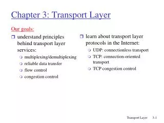
Outline • Design criteria and principles • Subsystems description • Photos • Status and overall schedule
Design Criteria and Principles • Deposit CsK2Sb photocathodes on the end of a removable cathode stalk for use in our 704 MHz SRF injector. • Additional capabilities for manufacturing and testing cesium dispenser photocathodes being developed by University of Maryland. • Install, remove, rejuvenate, & replace cathode without exposing source or cathode to atmosphere. • Deposit Cs, K, & Sb on cathode tip surface at pressures in the 10-10 to 10-9 Torr range. • Heat cathode as high as 850ºC for cleaning and maintain 130ºC to 150 ºC during deposition. • Remove & replace deposition sources without breaking deposition chamber vacuum. • Be able to negotiate BNL ERL facility labyrinth. • Provide capability for in-situ QE measurement.
Subsystems Description Deposition System • Deposition sources for Cs, K, and Sb • All-metal construction including gate valves-all bakeable to 250oC • 250 l/s ion pump with (2) NEGs, predictable base pressure 10-10torr range after bakeout • Radiant heater for cathode tip cleaning
Subsystems Description Cont’d Deposition System Cont’d • SAES alkali metal dispensers for Cs & K; heated baffled box for Sb • Rough pumping by oil-free TMP • Deposition process controlled by quartz crystal monitor • Laser port and collector for QE measurement
Subsystems Description Cont’d Transport System • Two vacuum crosses separated by long stroke bellows • 200 l/s Ion pump on front cross; 40 l/s pump on rear cross (additional NEGs) • All metal construction, all components bakeable to 250oC • (2) Dedicated transport carts for cathode assembly
Status and Overall Schedule Deposition System • Deposition system delivery from AES • All systems tested and modified where necessary • Redesign K and Sb source arms completed • Base pressure of 3.2 x 10⁻¹⁰ torr established • Awaiting source installation and 2500C bake
Status and Overall Schedule-Continued Transport Cart-1&2 • Delivery of both transport cart from AES • Unable to obtain base vacuum pressure • Both transport carts dissembled by BNL and AES • Parts cleaned at AES, vacuum baked at BNL • Ion pumps returned to GAMMA for rebuild • Redesign of cathode flexible cooling lines and TCs • Redesign of cathode stalk guide tube • Order placed for addition of NEG pumps
Commissioning Plan • The production of a cathode requires a transport cart tested and operational. • We look forward to producing a cathode and testing the deposition system when a transport cart becomes available, which we anticipate will be first quarter 2010.
Operation Instructions • Will be developed using an initial recipe for cathode production developed from the second generation deposition system • The AES deposition system uses similar technology to the second generation deposition system